-

-
Popular Posts
-
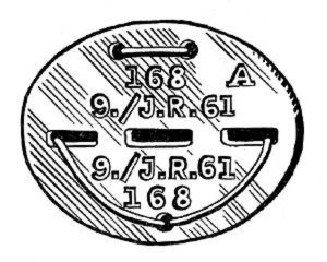 Erkennungsmarke (German Dog Tag)
From Handbook on German Army Identification, U.S. Milit...
Erkennungsmarke (German Dog Tag)
From Handbook on German Army Identification, U.S. Milit...
-
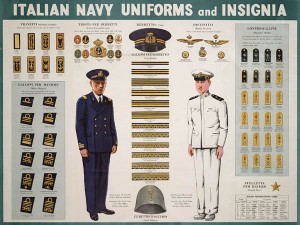 Italian Navy Uniforms and Insignia
:
CON...
Italian Navy Uniforms and Insignia
Italian Navy Uniforms and Insignia:
CON...
-
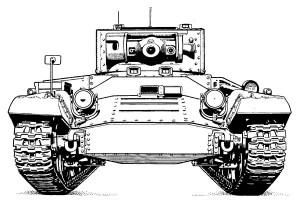 Valentine Tank Illustrations
Front and side views of the Valentine Tank (officially...
Valentine Tank Illustrations
Front and side views of the Valentine Tank (officially...
-
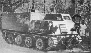 Japanese Type 1 Ho-Ki Armored Personnel Carrier
The Japanese produced a limited number of the innovativ...
Japanese Type 1 Ho-Ki Armored Personnel Carrier
The Japanese produced a limited number of the innovativ...
-
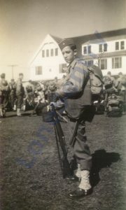 Early-War Uniform
A private photograph from 1942 showing details of the e...
Early-War Uniform
A private photograph from 1942 showing details of the e...
-
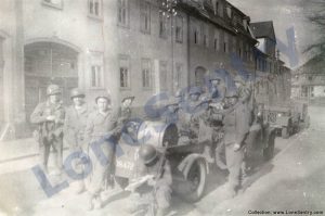 89th Infantry Division in Germany
Photographs of the U.S. Army's 89th Infantry ...
89th Infantry Division in Germany
Photographs of the U.S. Army's 89th Infantry ...
-
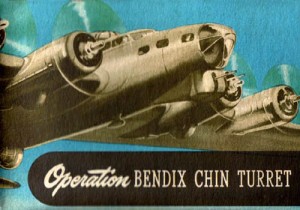 Bendix Chin Turret
Bendix manual on the Operation and Maintenance of the B...
Bendix Chin Turret
Bendix manual on the Operation and Maintenance of the B...
-
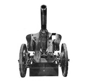 German 105-mm Howitzer
Three views of the German 105-mm howitzer (10.5 cm leFH...
German 105-mm Howitzer
Three views of the German 105-mm howitzer (10.5 cm leFH...
-
 How’s Your Sherman, Herman?
M4 Sherman Tank modification and upgrades from Army Mot...
How’s Your Sherman, Herman?
M4 Sherman Tank modification and upgrades from Army Mot...
-
Tag Archives: weapons
9-mm Luger Pistol M1908
The following report on the German Luger Pistole Parabellum 1908 was published in Foreign Military Weapons and Equipment, Vol. III, Infantry Weapons, Pamphlet No. 30-7-4, Department of the Army, 1954. 9-mm Luger Pistol M1908 (PISTOLE 08 or P-08) The … Continue reading
5-Inch Naval Gun Turret
An interesting cutaway drawing of the Mark 12 5″/38 caliber U.S. naval gun. (Source: Naval Ordnance and Gunnery, NAVPERS 16116, Bureau of Naval Personnel, Training Division, May 1944.)
9-mm Walther Pistol M1938
Brief article on the Walther P38 semi-automatic pistol from Foreign Military Weapons and Equipment, Vol. III, Infantry Weapons, Pamphlet No. 30-7-4, Department of the Army, 1954. 9-mm Walther Pistol M1938 (PISTOLE 38 or P-38) This weapon was steadily replacing the … Continue reading
Austrian Firearm Terms
Austrian Firearm Terms from Foreign Military Weapons and Equipment, Vol. III, Infantry Weapons, Pamphlet No. 30-7-4, Department of the Army, 1954. GLOSSARY OF AUSTRIAN TERMS Austrian Translation English Meaning PISTOLE Pistol Pistol GEWEHR Rifle Rifle KARABINER Carbine Carbine (short rifle) … Continue reading
Posted in miscellaneous, weapons
Tagged austrian, dictionary, firearms, guns, terms, translation, weapons
Comments Off on Austrian Firearm Terms
Machine Gun Turrets
Introduction to aircraft machine gun turrets from the WWII manual Index of Aeronautical Equipment with Navy and British Equivalents: Volume 5, Armament, March 1944. MACHINE GUN TURRETS (LOCAL CONTROL TYPES) The primary function of a machine gun turret is to … Continue reading
Japanese Infantry Weapons
Japanese Infantry Weapons: Source: Newsmap, U.S. Army Service Forces, Army Information Branch, December 11, 1944.
Aircraft Machine Guns
Caliber .30 and .50 Browning aircraft machine guns for aircraft from Index of Aeronautical Equipment with Navy and British Equivalents: Volume 5, Armament, March 1944. AIRCRAFT MACHINE GUNS Aircraft machine guns are used offensively or defensively against enemy aircraft or ground … Continue reading
32 cm Wurfkörper Flamm
Diagram of the 32 cm Wurfkörper Flamm incendiary rocket for the German Nebelwerfer from the German manual D 444/2839: Die Munition des 28/32 cm Nebelwerfers 41, Schweren Wurfrahmens 40 am gep Zgkw, Schweren Wurfgeräts 40, Schweren Wurfgeräts 41, 1943.
Posted in weapons
Tagged 32cm, flamm, incendiary, nebeltruppen, nebelwerfer, rocket, weapons, wurfkörper
Comments Off on 32 cm Wurfkörper Flamm
MP34 Submachine Gun (Steyr-Solothurn)
The following report on the MP 34 submachine gun was published in Foreign Military Weapons and Equipment, Vol. III, Infantry Weapons, Pamphlet No. 30-7-4, Department of the Army, 1954. 9-mm Submachine Gun MP 34 (Steyr-Solothurn) (MASCHINENPISTOLE MP 34) This weapon was … Continue reading
Posted in weapons
Tagged austria, gun, maschinenpistole, MP34, smg, solothurn, steyr, submachine gun, weapons
Comments Off on MP34 Submachine Gun (Steyr-Solothurn)
9-mm Pistol M12 Steyr
The following report on the Austrian 9-mm M12 Steyr Pistol was published in Foreign Military Weapons and Equipment, Vol. III, Infantry Weapons, Pamphlet No. 30-7-4, Department of the Army, 1954. 9-mm Pistol M12 Steyr (PISTOLE MOD M12 STEYR) This … Continue reading