-

-
Popular Posts
-
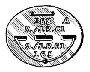 Erkennungsmarke (German Dog Tag)
From Handbook on German Army Identification, U.S. Milit...
Erkennungsmarke (German Dog Tag)
From Handbook on German Army Identification, U.S. Milit...
-
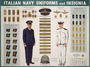 Italian Navy Uniforms and Insignia
:
CON...
Italian Navy Uniforms and Insignia
Italian Navy Uniforms and Insignia:
CON...
-
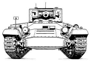 Valentine Tank Illustrations
Front and side views of the Valentine Tank (officially...
Valentine Tank Illustrations
Front and side views of the Valentine Tank (officially...
-
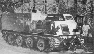 Japanese Type 1 Ho-Ki Armored Personnel Carrier
The Japanese produced a limited number of the innovativ...
Japanese Type 1 Ho-Ki Armored Personnel Carrier
The Japanese produced a limited number of the innovativ...
-
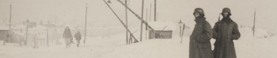
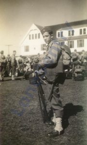 Early-War Uniform
A private photograph from 1942 showing details of the e...
Early-War Uniform
A private photograph from 1942 showing details of the e...
-
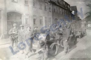 89th Infantry Division in Germany
Photographs of the U.S. Army's 89th Infantry ...
89th Infantry Division in Germany
Photographs of the U.S. Army's 89th Infantry ...
-
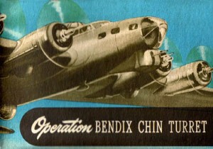 Bendix Chin Turret
Bendix manual on the Operation and Maintenance of the B...
Bendix Chin Turret
Bendix manual on the Operation and Maintenance of the B...
-
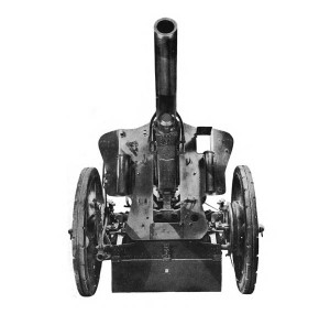 German 105-mm Howitzer
Three views of the German 105-mm howitzer (10.5 cm leFH...
German 105-mm Howitzer
Three views of the German 105-mm howitzer (10.5 cm leFH...
-
 How’s Your Sherman, Herman?
M4 Sherman Tank modification and upgrades from Army Mot...
How’s Your Sherman, Herman?
M4 Sherman Tank modification and upgrades from Army Mot...
-
Tag Archives: antiaircraft
AAA Ground Recognition Signals
The following comments from the commander of the U.S. 5th Armored Division on the proper use of ground recognition signals were published in “Antiaircraft Artillery Notes,” No. 5, November 22, 1944. Subject: Use of Ground Recognition Signals Source: AA Section, Headquarters Twelfth Army … Continue reading
Posted in aircraft, publications, research, weapons
Tagged AAA, antiaircraft, combat reports, flares, recognition, research, signals, training
Comments Off on AAA Ground Recognition Signals
M19 Twin 40-mm Gun Motor Carriage
Diagram of the M19 Twin 40-mm Gun Motor Carriage, from Technical Manual TM 9-1729A, U.S. War Department, 1944.
Fire Control
Fire control notes from the September 1944 issue of C.I.C. (Combat Information Center) published by the U.S. Office of the Chief of Naval Operations. fire control notes and comments… Excerpts from ship reports with comments by the Bureau of Ordnance. … Continue reading
Posted in combat reports, miscellaneous, navy, training
Tagged antiaircraft, fire control, navy, radar
Comments Off on Fire Control
537th AAA AW Bn in Action
Report on a small-unit action by Battery D, 537th AAA AW Bn from “Antiaircraft Artillery Notes,” HQ ETO, No. 3, November 1944: Subject: Gallantry in Action. Source: Antiaircraft Section, Headquarters Twelfth Army Group. a. Another outstanding example of individual gallantry, again … Continue reading
Posted in combat reports
Tagged 537th, antiaircraft, combat, france, le mans, silver star, surrender
Comments Off on 537th AAA AW Bn in Action
40mm Twin Mount and Crew
40mm twin mount and operating crew, from: Naval Ordnance and Gunnery, NAVPERS 16116, Bureau of Naval Personnel, Training Division, May 1944.
Dragon 1:72 88mm Flak 37
New 1/72nd-scale 88mm Flak 37 announcement from Dragon Models: #60634: 88mm FlaK 37, Eastern Front 1942-43.
Posted in scale models
Tagged 1/72nd, 88mm, antiaircraft, cannon, dragon, flak 37, gun
Comments Off on Dragon 1:72 88mm Flak 37
Cavalry Reconnaissance Antiaircraft Weapons
Antiaircraft security while moving: from Cavalry Field Manual FM 2-30: Cavalry Mechanized Reconnaissance Squadron, U.S. War Department, March 1943. SECURITY — While Moving. Antiaircraft weapons in all elements of the squadron are alerted for antiaircraft fire at all times. Whenever overhead … Continue reading
Posted in miscellaneous, training, weapons
Tagged antiaircraft, cavalry, field manual, jeep, security
Comments Off on Cavalry Reconnaissance Antiaircraft Weapons
90-mm Antiaircraft Gun Emplacement
Posted in miscellaneous, publications, training
Tagged 90mm, antiaircraft, bunker, defense, emplacement, gun, M1
Comments Off on 90-mm Antiaircraft Gun Emplacement
Japanese Aerial-Burst Bombs
Further intelligence reports on Japanese aerial-bombs used against Allied bombers: JAPANESE AERIAL-BURST BOMBS This article briefly outlines information received from the South Pacific regarding Japanese aerial-burst incendiary bombs. At the present time two types of Japanese bombs are known which … Continue reading
Posted in aircraft, intelligence reports, research, weapons
Tagged aerial bomb, antiaircraft, incendiary, japanese, tactics, weapons
Comments Off on Japanese Aerial-Burst Bombs
Japanese Model 88 75-mm AA Gun
Description of the WWII Japanese Model 88 (1928) 75-mm Antiaircraft Gun from Japanese Field Artillery, Special Series No. 25, Military Intelligence Division, U.S. War Department, Washington, D.C., October 15, 1944. Model 88 (1928) 75-mm AA Gun. Model 88 (1928) 75-mm AA gun … Continue reading