-

-
Popular Posts
-
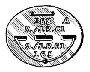 Erkennungsmarke (German Dog Tag)
From Handbook on German Army Identification, U.S. Milit...
Erkennungsmarke (German Dog Tag)
From Handbook on German Army Identification, U.S. Milit...
-
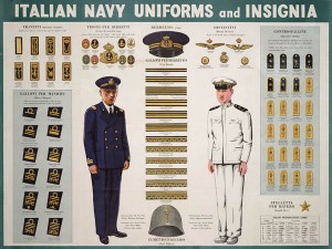 Italian Navy Uniforms and Insignia
:
CON...
Italian Navy Uniforms and Insignia
Italian Navy Uniforms and Insignia:
CON...
-
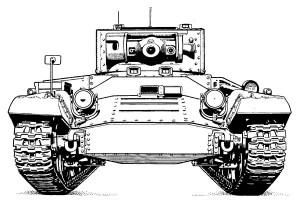 Valentine Tank Illustrations
Front and side views of the Valentine Tank (officially...
Valentine Tank Illustrations
Front and side views of the Valentine Tank (officially...
-
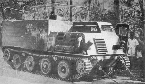 Japanese Type 1 Ho-Ki Armored Personnel Carrier
The Japanese produced a limited number of the innovativ...
Japanese Type 1 Ho-Ki Armored Personnel Carrier
The Japanese produced a limited number of the innovativ...
-
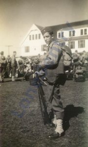 Early-War Uniform
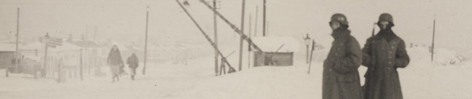
A private photograph from 1942 showing details of the e...
Early-War Uniform
A private photograph from 1942 showing details of the e...
-
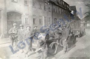 89th Infantry Division in Germany
Photographs of the U.S. Army's 89th Infantry ...
89th Infantry Division in Germany
Photographs of the U.S. Army's 89th Infantry ...
-
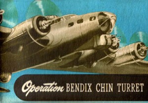 Bendix Chin Turret
Bendix manual on the Operation and Maintenance of the B...
Bendix Chin Turret
Bendix manual on the Operation and Maintenance of the B...
-
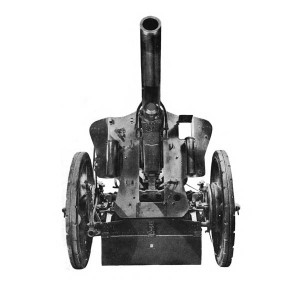 German 105-mm Howitzer
Three views of the German 105-mm howitzer (10.5 cm leFH...
German 105-mm Howitzer
Three views of the German 105-mm howitzer (10.5 cm leFH...
-
 How’s Your Sherman, Herman?
M4 Sherman Tank modification and upgrades from Army Mot...
How’s Your Sherman, Herman?
M4 Sherman Tank modification and upgrades from Army Mot...
-
Tag Archives: turret
SBS Model Toldi Sets
SBS Model has released three new 1/35th-scale resin and photoetch sets for the Hobbyboss Toldi I kit — 35014: 1/35 Toldi Tools and Equipment (Toldi I, Toldi II, Toldi III) for Hobbyboss Kit; 35015: 1/35 Toldi I (B20) corrected turret (without barrel) for … Continue reading
A-26 Upper Turret Angles
Diagram of the upper turret fire interruption angles for the A-26, from: Pilot’s Handbook for Army Models A-26B and A-26C Airplanes, AN 01-40AJ-1, August 1945, revised January 1946. This illustration shows the gunfire intercepting areas and the margins of interruption (approximately) and … Continue reading
Naval Twin 5-Inch Turret
Details of the twin mount 5-inch/38 cal. naval gun from Naval Ordnance and Gunnery, NAVPERS 16116, Bureau of Naval Personnel, Training Division, May 1944.)
5-Inch Naval Gun Turret
An interesting cutaway drawing of the Mark 12 5″/38 caliber U.S. naval gun. (Source: Naval Ordnance and Gunnery, NAVPERS 16116, Bureau of Naval Personnel, Training Division, May 1944.)
Machine Gun Turrets
Introduction to aircraft machine gun turrets from the WWII manual Index of Aeronautical Equipment with Navy and British Equivalents: Volume 5, Armament, March 1944. MACHINE GUN TURRETS (LOCAL CONTROL TYPES) The primary function of a machine gun turret is to … Continue reading
How to Jettison a PB4Y Ball Turret
Procedure to jettison the nose ball turret in the PB4Y from Naval Aviation News, August 1944. How to Jettison a Turret PB4Y Gets Back Safe from Saipan A Navy photographic plane came back from a mission over Saipan recently after battling … Continue reading
Thanks to the Power Turret… The Bomber Fights Back
The importance of the modern power gun turret to U.S. bombers in WW2 from Aircrewman’s Gunnery Manual, Aviation Training Division, Office of the Chief of Naval Operations, U.S. Navy, 1944 Thanks to the Turret… THE BOMBER FIGHTS BACK Without the … Continue reading
Erco Ball Turret
Illustrations and performance details of the Erco 250SH Ball Turret mounted in the PB4Y Privateer from Aircrewman’s Gunnery Manual, Aviation Training Division, Office of the Chief of Naval Operations, U.S. Navy, 1944. Erco Ball Turret ERCO 250SH-2, 2A or 3 … Continue reading
Bendix Chin Turret
Bendix manual on the Operation and Maintenance of the Bendix Chin Turret for the B-17 Flying Fortress: GENERAL SPECIFICATIONS Armament Two Caliber .50 M-2 machine guns. Ammunition Capacity 450 rounds per gun. Speed of Turret Slow speed (tracking) … Continue reading
Erco Tear Drop Turret
Illustrations and performance details of the Erco 250TH Tear Drop Turrets mounted in the PB4Y-2 Privateer from Aircrewman’s Gunnery Manual, Aviation Training Division, Office of the Chief of Naval Operations, U.S. Navy, 1944. ERCO TEAR DROP TURRET ERCO 250TH-1 AND … Continue reading