-

-
Popular Posts
-
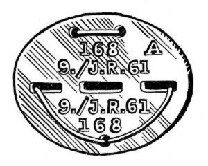 Erkennungsmarke (German Dog Tag)
From Handbook on German Army Identification, U.S. Milit...
Erkennungsmarke (German Dog Tag)
From Handbook on German Army Identification, U.S. Milit...
-
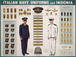 Italian Navy Uniforms and Insignia
:
CON...
Italian Navy Uniforms and Insignia
Italian Navy Uniforms and Insignia:
CON...
-
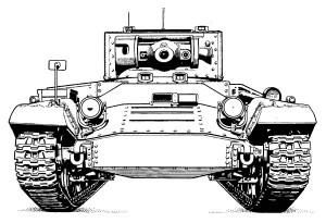 Valentine Tank Illustrations
Front and side views of the Valentine Tank (officially...
Valentine Tank Illustrations
Front and side views of the Valentine Tank (officially...
-
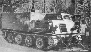 Japanese Type 1 Ho-Ki Armored Personnel Carrier
The Japanese produced a limited number of the innovativ...
Japanese Type 1 Ho-Ki Armored Personnel Carrier
The Japanese produced a limited number of the innovativ...
-
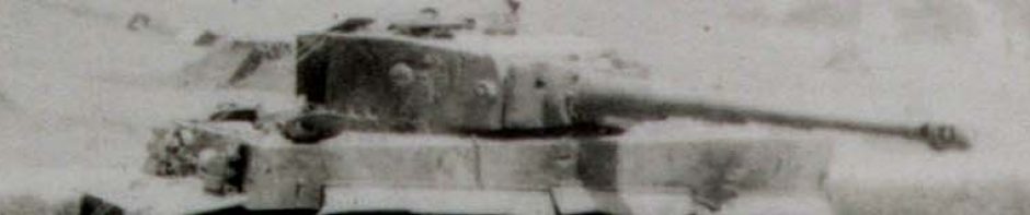
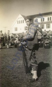 Early-War Uniform
A private photograph from 1942 showing details of the e...
Early-War Uniform
A private photograph from 1942 showing details of the e...
-
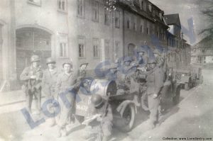 89th Infantry Division in Germany
Photographs of the U.S. Army's 89th Infantry ...
89th Infantry Division in Germany
Photographs of the U.S. Army's 89th Infantry ...
-
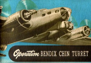 Bendix Chin Turret
Bendix manual on the Operation and Maintenance of the B...
Bendix Chin Turret
Bendix manual on the Operation and Maintenance of the B...
-
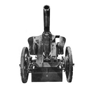 German 105-mm Howitzer
Three views of the German 105-mm howitzer (10.5 cm leFH...
German 105-mm Howitzer
Three views of the German 105-mm howitzer (10.5 cm leFH...
-
 How’s Your Sherman, Herman?
M4 Sherman Tank modification and upgrades from Army Mot...
How’s Your Sherman, Herman?
M4 Sherman Tank modification and upgrades from Army Mot...
-
Tag Archives: antitank
M1 57mm Anti-tank Gun Kit
Riich.Models has announced a new 1/35th-scale WWII anti-tank gun release: RV 35020: U.S. M1 57mm Anti-tank Gun on M2 carriage (Late Version). The M1 served as the standard towed anti-tank gun of the U.S. infantry divisions and over 10,000 guns were … Continue reading
Posted in scale models
Tagged 57mm, antitank, carriage, gun, M1, riich models
Comments Off on M1 57mm Anti-tank Gun Kit
Dragon “Chow Time” Antitank Crew Kit
Dragon Models has announced their upcoming 1/35th-scale figure kit depicting a German antitank crew eating a winter meal on the Eastern Front: Item No. 6697 – 1/35th-Scale “Chow Time” German Anti-Tank Gun Crew (Eastern Front). The kit includes three figures … Continue reading
Posted in scale models
Tagged 37mm, antitank, dragon, eastern front, figures
Comments Off on Dragon “Chow Time” Antitank Crew Kit
Plusmodel Antitank Grenades & Panzerfaust
Two recent 1/35th anti-tank weapon releases from the Czech company plusmodel — No.: EL055, 1/35 Panzerfaust 60 and No.: EL057, 1/35 Antitank Grenades. Both kits are MSRP: 4.60 USD, 3.30 EUR.
Posted in scale models
Tagged antitank, grenade, panzerfaust, plusmodel
Comments Off on Plusmodel Antitank Grenades & Panzerfaust
Bazooka Emplacement
Bazooka emplacements from the Corps of Engineers’ field manual FM 5-15: Field Fortifications, U.S. War Department, February 1944. 43. ROCKET LAUNCHER EMPLACEMENT. There are two types of emplacement for this weapon, the pit-foxhole type and the pit type. a. Pit-foxhole type … Continue reading
Posted in miscellaneous, training, weapons
Tagged antitank, bazooka, emplacement, foxhole, pit, rocket launcher, rocketeer
Comments Off on Bazooka Emplacement
Zvezda British 6 pdr Anti-Tank Gun
New 1/35th-scale kit from Zvezda of the British Anti-Tank Gun QF 6-PDR MK-II (Item No. 3518).
37-mm Ammunition Comparison
Comparison of 37-mm Ammunition from WW2 technical manual: TM 9-1901: Artillery Ammunition, War Department Technical Manual, June 1944: FIXED AND SEMIFIXED ROUNDS AND SEPARATE-LOADING PROJECTILES: A – MK.II A1, PRACTICE ROUND FOR 37-MM GUN SUBCALIBER, M1916 B – M56 H.E ROUND FOR 37-MM GUNS, … Continue reading
Posted in miscellaneous, research, weapons
Tagged 37mm, ammunition, antitank, projectile, rounds
Comments Off on 37-mm Ammunition Comparison
Bazooka Operation in Hot & Cold Climates
Operating instructions for the Bazooka in tropical and arctic climates from TM 9-294: 2.36-inch A.T. Rocket Launcher M1A1, War Department Technical Manual, Sept. 27, 1943. Section X: OPERATION UNDER UNUSUAL CONDITIONS 32. GENERAL. a. When operating under unusual conditions such … Continue reading
Posted in miscellaneous, publications, training, weapons
Tagged antitank, bazooka, climate, cold, hot, rocket launcher, weapons
1 Comment
Bazooka Versus Tank
The history of the bazooka from U.S. Rocket Ordnance: Development and Use in World War II, U.S. Joint Board on Scientific Information Policy, 1946. Bazooka Versus Tank Among the now-it-can-be-told weapons of the American rocket family, is the super-bazooka, bigger … Continue reading
Ju 87G Kanonenvogel
Original Bundesarchiv Caption: Sowjetunion.- Flugzeug Junkers Ju 87 G “Stuka” mit 3,7-cm-Kanonen FlaK 18 (“Kanonenvogel”) auf einem Feldflugplatz; PK Lw zbV. This photograph file is licensed under the Creative Commons Attribution-Share Alike 3.0 Germany license. Attribution: Bundesarchiv, Bild 101I-646-5184-26 / … Continue reading
Posted in aircraft, photos
Tagged antitank, bordkanone, bundesarchiv, cannon, Ju87, junkers, kanonenvogel, photos, stuka
Comments Off on Ju 87G Kanonenvogel