-

-
Popular Posts
-
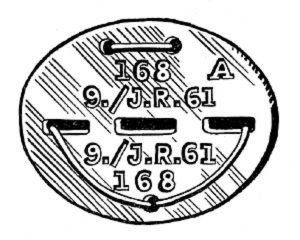 Erkennungsmarke (German Dog Tag)
From Handbook on German Army Identification, U.S. Milit...
Erkennungsmarke (German Dog Tag)
From Handbook on German Army Identification, U.S. Milit...
-
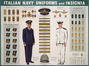 Italian Navy Uniforms and Insignia
:
CON...
Italian Navy Uniforms and Insignia
Italian Navy Uniforms and Insignia:
CON...
-
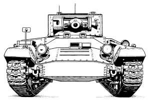 Valentine Tank Illustrations
Front and side views of the Valentine Tank (officially...
Valentine Tank Illustrations
Front and side views of the Valentine Tank (officially...
-
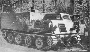 Japanese Type 1 Ho-Ki Armored Personnel Carrier
The Japanese produced a limited number of the innovativ...
Japanese Type 1 Ho-Ki Armored Personnel Carrier
The Japanese produced a limited number of the innovativ...
-
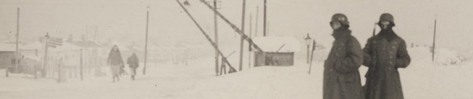
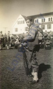 Early-War Uniform
A private photograph from 1942 showing details of the e...
Early-War Uniform
A private photograph from 1942 showing details of the e...
-
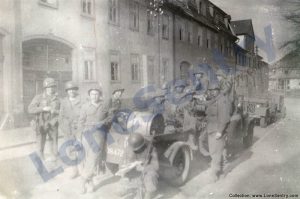 89th Infantry Division in Germany
Photographs of the U.S. Army's 89th Infantry ...
89th Infantry Division in Germany
Photographs of the U.S. Army's 89th Infantry ...
-
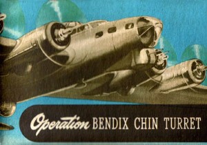 Bendix Chin Turret
Bendix manual on the Operation and Maintenance of the B...
Bendix Chin Turret
Bendix manual on the Operation and Maintenance of the B...
-
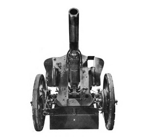 German 105-mm Howitzer
Three views of the German 105-mm howitzer (10.5 cm leFH...
German 105-mm Howitzer
Three views of the German 105-mm howitzer (10.5 cm leFH...
-
 How’s Your Sherman, Herman?
M4 Sherman Tank modification and upgrades from Army Mot...
How’s Your Sherman, Herman?
M4 Sherman Tank modification and upgrades from Army Mot...
-
Category Archives: weapons
M10 Tank Destroyers on Railcar
M10 tank destroyers, halftracks, and motorcycles are shown loaded on railcars in the United States. The boxcar in the background carries the emblem of the Chicago and North Western Line (CNW).
Posted in armor, photos, weapons
Tagged halftrack, M10, motorcycle, railcar, tank destroyer, TD, train
Comments Off on M10 Tank Destroyers on Railcar
Captured Tiger Tank Photo Op
The U.S. bazooka and the German Panzerschreck are posed in front of a captured German Tiger tank. (Source: Army Ordnance, Volume 27, No. 145, July-August 1944.) Original caption: The German 88-mm. rocket launcher is shown with the American bazooka beside … Continue reading
Wreckage in Italy
Various photographs of Axis wreckage taken by a U.S. soldier moving up the Italian boot during WWII. The quality is rather poor as the photos appear to have been taken from a moving vehicle. A Panzer IV abandoned on the … Continue reading
Bachem Ba 349 Natter
A report on the Bachem Ba 349 “Natter” rocket-powered fighter from April 1946 issue of Intelligence Bulletin: At first complacent in the face of the strategic bombing threat, the Germans in 1943 became fearful, then frantic. They were willing to … Continue reading
Sherman Tank Wrecks in Italy
Destroyed Sherman tanks photographed in Italy during WWII; unfortunately, the photos are low quality and unlabeled.
Destroyed Late-War Panther Tanks
Captured German Panther tanks are shown in three photographs from the unit history of the U.S. Army’s 407th Infantry Regiment, 102nd Infantry Division. The source does not specify a location, but the text suggests the location is near Fallersleben, Germany … Continue reading
Posted in armor, combat reports, miscellaneous, photos, weapons
Tagged 102nd infantry division, 407th infantry regiment, panther, panzer v
Comments Off on Destroyed Late-War Panther Tanks
Dummy Tanks in France
A report from the Intelligence Bulletin, December 1944 on the German use of dummy Panther tanks during World War II. The report includes two photographs of a dummy tank encountered in France in 1944. DUMMY TANKS Although German use of … Continue reading
Posted in armor, intelligence reports, publications, weapons
Tagged 1944, camouflage, dummy tanks, france, normandy
Comments Off on Dummy Tanks in France
Jagdtigers Surrender to 99th Infantry Division
In April 1945, Jagdtigers (Panzerjäger Tiger Ausf. B) of s.Pz.Jäg.Abt. 512 surrended to the U.S. 99th Infantry Division in Iserlohn at the Schillerplatz. The illustrations shown here are from the WWII G.I. Stories booklet Battle Babies: The Story of the … Continue reading
Posted in armor, combat reports, photos, publications, weapons
Tagged 99th infantry division, iserlohn, jagdtiger, schillerplatz
Comments Off on Jagdtigers Surrender to 99th Infantry Division
Captured German Equipment
Wartime U.S. Army Signal Corp photographs of captured German equipment from 1944-1945 issues of the U.S. military training magazine Coastal Artillery with original captions. A Mark V, La Gleize
Posted in armor, artillery, intelligence reports, photos, weapons
Tagged captured, equipment, flak, heavy artillery
Comments Off on Captured German Equipment
995th Field Artillery Battalion #2
S/Sgt. Tex Roberson photographed with an 8-inch howitzer of the 995th Field Artillery Battalion. See also: 995th Field Artillery Battalion Photo Album. (Collection LoneSentry.com)