
-

-
Popular Posts
-
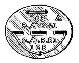 Erkennungsmarke (German Dog Tag)
From Handbook on German Army Identification, U.S. Milit...
Erkennungsmarke (German Dog Tag)
From Handbook on German Army Identification, U.S. Milit...
-
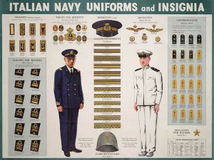 Italian Navy Uniforms and Insignia
:
CON...
Italian Navy Uniforms and Insignia
Italian Navy Uniforms and Insignia:
CON...
-
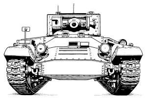 Valentine Tank Illustrations
Front and side views of the Valentine Tank (officially...
Valentine Tank Illustrations
Front and side views of the Valentine Tank (officially...
-
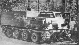 Japanese Type 1 Ho-Ki Armored Personnel Carrier
The Japanese produced a limited number of the innovativ...
Japanese Type 1 Ho-Ki Armored Personnel Carrier
The Japanese produced a limited number of the innovativ...
-
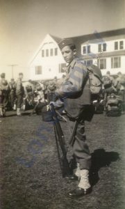 Early-War Uniform
A private photograph from 1942 showing details of the e...
Early-War Uniform
A private photograph from 1942 showing details of the e...
-
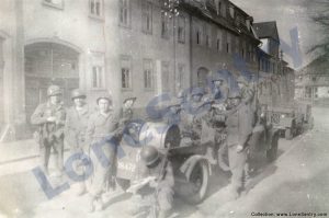 89th Infantry Division in Germany
Photographs of the U.S. Army's 89th Infantry ...
89th Infantry Division in Germany
Photographs of the U.S. Army's 89th Infantry ...
-
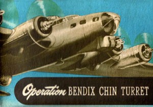 Bendix Chin Turret
Bendix manual on the Operation and Maintenance of the B...
Bendix Chin Turret
Bendix manual on the Operation and Maintenance of the B...
-
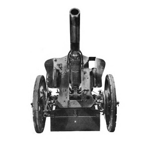 German 105-mm Howitzer
Three views of the German 105-mm howitzer (10.5 cm leFH...
German 105-mm Howitzer
Three views of the German 105-mm howitzer (10.5 cm leFH...
-
 How’s Your Sherman, Herman?
M4 Sherman Tank modification and upgrades from Army Mot...
How’s Your Sherman, Herman?
M4 Sherman Tank modification and upgrades from Army Mot...
-
Tag Archives: ordnance
OIS 157th Ordnance Photo Set
Below is a small set of photographs from an unidentified unit in Europe. The bumper code markings on the truck are OIS-157-O which may represent Oise Intermediate Section (OIS), 157th Ordnance Battalion. (However, the unit identification is uncertain, since 157th … Continue reading
Don’t Be A Dope VI
An illustration from the “Don’t be a Dope!” series was included in the M36 tank destroyer technical manual.
M3 Medium Tank Armament
Diagram of the armament and ammunition storage of the M3 Medium Tank. (Source: TM 9-750: Ordnance Maintenance, Medium Tanks M3, M3A1, and M3A2, Technical Manual, U.S. War Department, May 1942.)
Naval 3-Inch Mark 21 Mount
Left and right-side views of the Mark 21 mount for the 3-inch/50 cal. naval gun from Naval Ordnance and Gunnery, NAVPERS 16116, Bureau of Naval Personnel, Training Division, May 1944.
Aircraft Machine Guns
Caliber .30 and .50 Browning aircraft machine guns for aircraft from Index of Aeronautical Equipment with Navy and British Equivalents: Volume 5, Armament, March 1944. AIRCRAFT MACHINE GUNS Aircraft machine guns are used offensively or defensively against enemy aircraft or ground … Continue reading
Don’t Be A Dope V
Always check the oil! An angry tank crew stars in another “Don’t Be A Dope” training poster from Aberdeen Proving Grounds. The tank crew is sore as a boil For it ain’t according to Hoyle To get caught in … Continue reading
Don’t Be A Dope IV
Another in the colorful series of “Don’t Be A Dope” training posters starring Joe Dope: Don’t wash vehicles in lakes, creeks or oceans, it ruins and corrodes delicate parts. Don’t be a dope! HANDLE EQUIPMENT RIGHT.
Don’t Be A Dope III
Another “Don’t Be A Dope” training poster starring Joe Dope: When the Stukas begin to attack Ain’t the time to make up for a lack Of cleaning your gun – Which won’t shoot at a Hun With a month’s gummy … Continue reading
How’s Your Dodge, Rog?
“How’s Your Dodge, Rog?” from Army Motors, Chief of Ordnance, August 1944.
Posted in miscellaneous, training
Tagged army motors, dodge, equipment, maintenance, ordnance
1 Comment
Don’t Be A Dope II
Another humorous “Don’t be a dope!” poster from WWII. Don’t be a dope! Handle Equipment Right! With an air of complete unconcern // Joe Dope speeds his Jeep ’round a turn // And slams on his brakes //At each stop … Continue reading