
GENERAL SPECIFICATIONS
Armament
Two Caliber .50 M-2 machine guns.
Ammunition Capacity 450 rounds per gun.
Speed of Turret
Slow speed (tracking) ¼° per second to 12° per second.
High speed (slewing, with high speed button depressed) ¼° per second to 33° per second.
Weights
Turret Complete (no guns or ammunition) 438 lbs.
Ammunition 33 lbs. per 100 rounds.
Guns 65 lbs. each.
Gear Drive
Speed Reducer ratio 25-1.
Azimuth gear ratio 50-1.
Elevation gear ratio 42-1.
Azimuth gear train reduction 1250-1.
Elevation gear train reduction 1050-1.
Electrical Requirements
24 Volt D.C.
Peak starting current motor amplidynes 1280 amps.
Maximum current draw running full load 92 amps.
Maximum current draw running no load 40 amps.
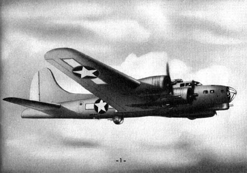
GENERAL DESCRIPTION
BENDIX CHIN TURRET
The Bendix Chin Turret Model “D” is an electrically driven power turret, mounting two caliber, .50 M-2 Machine Guns, equipped with recoil absorbing mechanism, firing solenoids, and manual gun chargers.
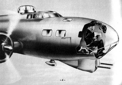
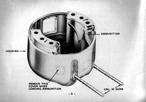
The turret is designed to be mounted in the Bombardier’s Compartment and to be operated by the Bombardier to protect the forward approaches to the ship. The guns rotate 172° in azimuth (86° to the left and to the right of forward) and swing from 26° above horizontal to 46° below horizontal. Switch limits are adjustable. The turret is mounted at floor level in the Bombardier’s Compartment. The guns extend below the fuselage at the nose of the ship. The lower assembly, with the exception of the gun barrels which protrude through covered slots, is enclosed in an aluminum, movable housing to minimize wind resistance. Plexiglass windshields seal the space at the floor of the ship around the turret.
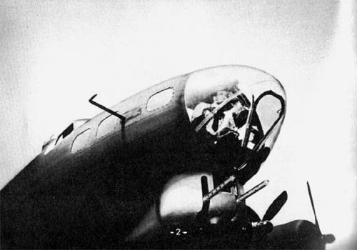
Ammunition containers are fixed to the movable housing and are equipped with guide chutes which permit ammunition to flow to the guns while they are rotating in elevation and in azimuth. The empty case and belt links are ejected by chutes through the bottom of the housing.
The Bombardier is the Chin Turret Gunner, and operates the Chin turret from the Bombardier’s position by lifting a latch and swinging the turret controller from its stowed position against the right side of the fuselage to the combat position which is at a convenient height in front of the gunner. The main power switch is located on the controller column at the front of the controller. The sight is suspended at eye level from the top of the fuselage above the operators position.
The direction and speed of the guns are controlled by handle bar type control handles. Each handle contains a safety brake switch for stopping the turret should the gunner relax his grip; a spring trigger switch for firing the guns, and a high speed switch for fast tracking speeds. Movements of the control handle in azimuth and in elevation move potentiometers which vary the control fields of azimuth and elevation Amplidyne generators. The variable out put of the Amplidyne generators control the direction and speed of the azimuth and elevation turret driving motors. The speed of the turret can be varied from ¼° per second to 12° per second in low speed and from ¼° to 33° per second in high speed. The Amplidyne system of control automatically furnishes a constant speed for any setting of the control handles regardless of the change of torque.
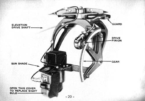
The open sight is synchronized with the movements of the gun in azimuth and in elevation and is driven by tachometer shafts from the azimuth and elevation gear trains. The gunner’s field of view thus always includes the direction in which the guns are pointing and moves with the guns. The sight is equipped with a rheostat to control the intensity of the light of the circle which is projected on the sight glass.
The center of the field of view is marked by the center dot and is the point on which the guns are trained. The dot and circle are used in the same manner as a ring sight and bead on a flexible machine gun installation. The intensity of the light can be varied to satisfy the operating conditions of bright sunlight or night flying.
To operate the turret the Bombardier lifts the control column latch and swings the controller and column from the stowed position to the combat position, moves the power switch to the power position, charge the guns, and adjusts the intensity of the sight reticle to the light conditions. The movements of the guns in azimuth and in elevation are controlled by the handle bar type control handles. The turret can be operated only when the safety switch on the outside of either control handle is depressed. Rotation of turret in azimuth follows rotation of the control handles clockwise or counterclockwise about the vertical axis. The swing of the guns in elevation follows swing of the control handles up or down. The speed of the guns is proportional to the degree of movement of the control handles from the neutral position in low speed. The guns are moved in high speed by depressing the high speed button on the top of either control handle. High speed of the guns is proportional to the degree of movement of the control handles from the neutral position. Looking through the sight, the gunner trains the guns on the target by moving the control handles. The guns are fired by pressing the trigger switch on the front of either control handle.
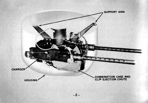
The gunner can follow a target freely, firing as required without the guns striking the fuselage or firing into any part of the ship. The limits of the gun movements in azimuth and elevation are automatically controlled by switches.
The turret can be stopped by releasing the control handle safety switches on the side of the control handles. The power supply to the turret is cut off by moving the main power switch to the “OFF” position. The turret can rotate in azimuth and the guns swung in elevation by use of a hand crank in the event of electric power failure.
OPERATION
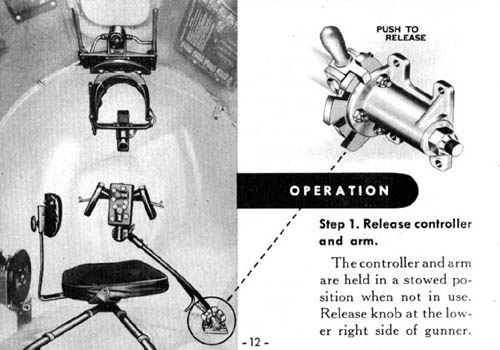
Step 1. Release controller and arm.
The controller and arm are held in a stowed position when not in use. Release knob at the lower right side of gunner.
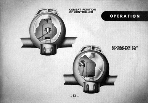
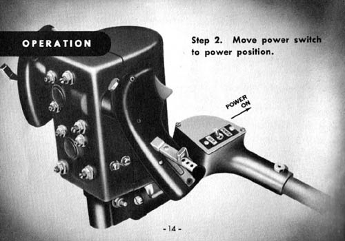
Step 2. Move power switch to power position.
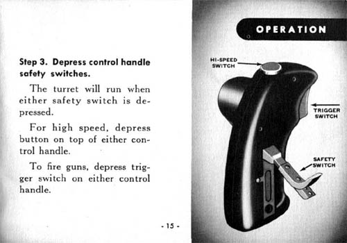
Step 3. Depress control handle safety switches.
The turret will run when either safety switch is depressed.
For high speed, depress button on top of either control handle.
To fire guns, depress trigger switch on either control handle.
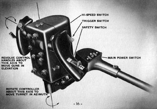
Step 4. Controller.
To raise or lower the guns in elevation rotate control handles about the horizontal axis. To rotate the turret in azimuth, move controller about vertical axis. Turret moves in same relative direction as controller is turned, the speed being proportional to the degree of movement of the control handles from the neutral position.
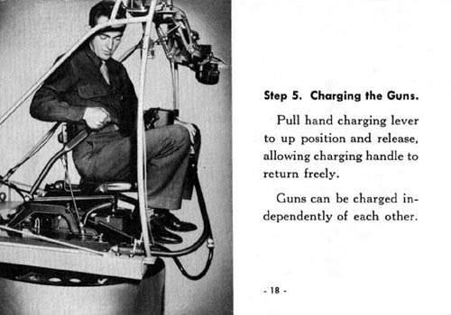
Step 5. Charging the Guns.
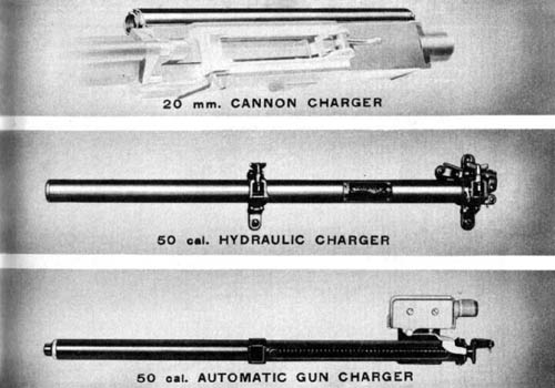
Pull hand charging lever to up position and release, allowing charging handle to return freely.
Guns can be charged independently of each other.
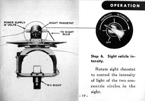
Step 6. Sight reticle intensity.
Rotate sight rheostat to control the intensity of light of the two concentric circles in the sight.
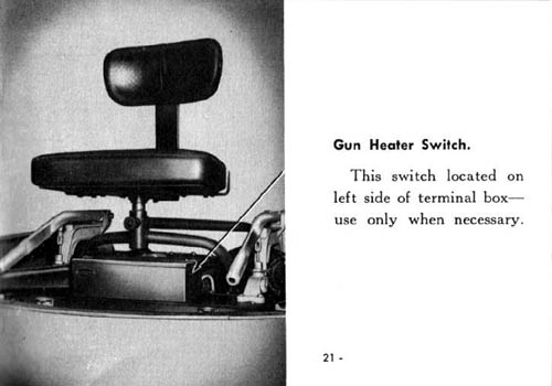
Gun Heater Switch.
This switch located on left side of terminal box—use only when necessary.
MAINTENANCE
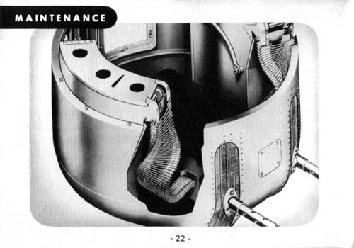
Loading ammunition.
The shells are loaded into the ammunition container so that they point towards the center column. Thread the end of the ammunition belt that extends from the top layer of the ammunition container through the guide rails. The shells now point the same direction as the guns. Insert the belt with the double link first into the ammunition feed way of the gun until the cartridge holding pawl is actuated.
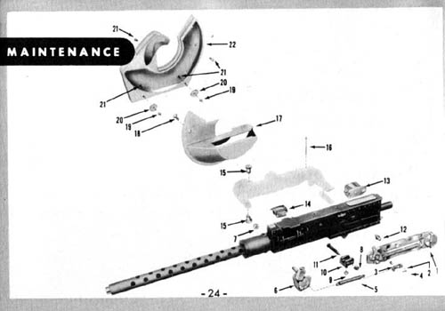
The following accessories are added to the caliber .50 machine gun when used on the Bendix Chin Turret.
1. MANUAL CHARGER
2. CLEVIS FOR CHARGER
3. CLEVIS PIN FOR CHARGER
4. COTTER PIN FOR CHARGER
5. SPRING
6. FRONT PULLEY
7. NUT
8. NUT
9. NUT
10. RECOIL GUIDE
11. BOLT
12. CHARGING PIN
13. SOLENOID
14. AUXILIARY CLIP CHUTE
15. YOKE STUD
16. BOLT
17. CASE EJECTION CHUTE
18. FLAT HEAD SCREW
19. NUT
20. ROLLER
21. CLIP CHUTE MOUNTING BOLT
22. CLIP CHUTE
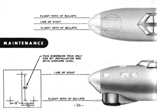
Harmonization of sight and guns.
The turret is provided with adjustments for the machine guns and sight which will permit the guns and sight to be set up for parallel or converging fire. For parallel fire the flight path of the bullets from the two guns and the sight line are all parallel. The guns are mounted so that the flight path of the bullets are in a horizontal plane 56.6″ below the sight line. With the guns straight forward the flight path of the bullets are 7½” to either side of a vertical plane passed through the sight line.
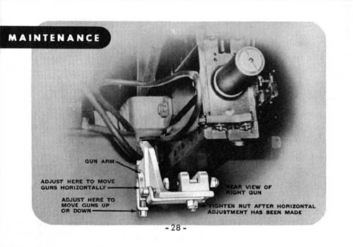
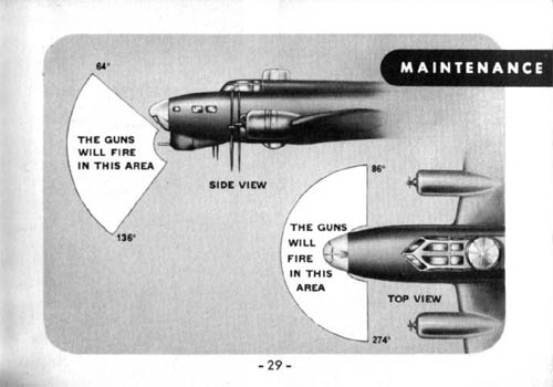
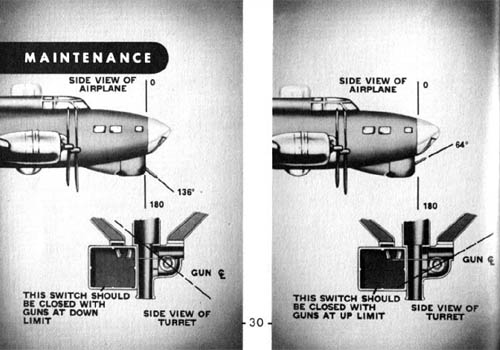
Adjustment of elevation limit micro-switches.
PROCEDURE.
(1) Remove the entire movable housing by removing the bolts, that hold the housing to the arms, and four button head screws holding housing to foot casting.
(2) Remove right hand side cover plate from relay box.
ADJUSTMENT.
(3) Crank guns to down limit 136° zenith (check with protractor level). Foot of elevation limit rack should just actuate down limit switch at this point. Loosen adjusting screw and slide limit switch stop until micro switch just closes. (Check with ohmmeter.)
(4) Crank guns to up limit 64° zenith (check with protractor level) foot of elevation limit rack should just actuate up limit switch at this point. Loosen adjusting screw and slide limit switch stop until foot of elevation limit rack just actuates up limit micro switch.
Adjustment of azimuth limit switches.
PROCEDURE.
(1) Remove movable housing.
ADJUSTMENT.
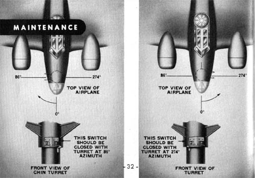
(1) Using hand crank rotate guns clockwise to 86° azimuth, turn adjusting screw on azimuth limit switch lever to actuate micro-switch as arm just raises lever.
(2) Rotate guns counter-clockwise to 274° azimuth and perform same adjustment for counter-clockwise limit switch.
Compounding instructions Model “D”.
PROCEDURE.
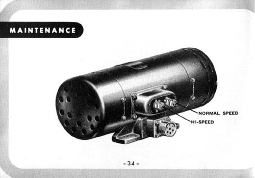
(1) Loosen locking nuts of the compounding rheostats located on the sides of the amplidyne. If the turret slows down under load turn the rheostat in the direction of the arrow, until it runs at a constant speed under load. If the turret speeds up under load turn the adjusting rheostat in the opposite direction from that of the arrow, until it will run at a constant speed under load.
(2) Depress high speed button and set high speed compounding adjustment at a low RPM (no load) so that no change in RPM occurs when the turret is loaded, that is applying a 40 lb. load to the front of the gun arm.
(3) Release high speed button and set the normal speed compounding adjustment at a low RPM (no load) so that there is no change in RPM when the turret is loaded, that is applying a 40 lb. load to the end of the gun arm.
(4) Tighten both locking nuts on the compounding adjustment.
(5) The above procedure must be followed for both azimuth and elevation.
Greasing.
To check the grease level of the azimuth gear assembly, unscrew the Allen head cap screw located in the center of the inspection panel on the side of the azimuth gear housing at the bottom of the center column. The grease must be at this level, if below it is necesary to add grease. The plug on the top of the azimuth gear housings is removed to fill with grease to proper level.
To check the grease in the speed reducer, back out the Allen head screw in the center of the side inspection plate. If the grease is not up to this height, remove top inspection plate and add grease.
The elevation gear housing grease level is checked by removing the plug on the side of the gear housing. Grease is added through the plug hole on top of the gear housing.
Maintenance checks.
1. Be sure turret is supplied with 20 volts or more for proper operation.
2. Check all firing limits and dynamic brakes by swinging turret in azimuth and elevation against all stops.
Note the guns do not strike fuselage or fire into any part of the ship.
3. Inspect sight for illuminated reticle. If reticle fails to light, switch to other filament. Switch for this is located on side of sight.
4. Ammunition containers should be filled and ammunition threaded into guns properly.
5. Charge the guns to be sure that charger is functioning.
6. Depress the interphone switch to test the ship’s interphone system.
7. Be sure that the guns and sight are harmonized correctly.
|
That was another really interesting article, just like the one on the Privateer waist guns blisters, as I’ve always wondered about the specifics of how this turret operated also.
Thanks for putting together this fantastic site.
On the Spitfire, the trigger appears to be on the left side of the “stick”. Why, since most folks are right handed and would seem more natural?
Nice article to read. I had to pass this along to a friend who is into these kind of things.
A most informative article, full of interesting detail. I had always wondered how this turret operated. Now I know.
Kind regards
Mark Jerrat.
Pingback: Mans En Garde: YB-40 - Koppen Krant