
-

-
Popular Posts
-
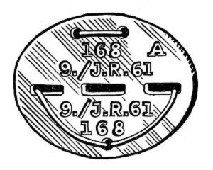 Erkennungsmarke (German Dog Tag)
From Handbook on German Army Identification, U.S. Milit...
Erkennungsmarke (German Dog Tag)
From Handbook on German Army Identification, U.S. Milit...
-
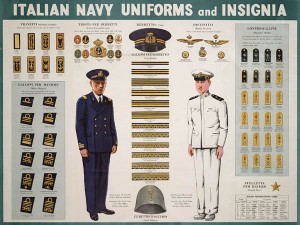 Italian Navy Uniforms and Insignia
:
CON...
Italian Navy Uniforms and Insignia
Italian Navy Uniforms and Insignia:
CON...
-
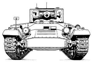 Valentine Tank Illustrations
Front and side views of the Valentine Tank (officially...
Valentine Tank Illustrations
Front and side views of the Valentine Tank (officially...
-
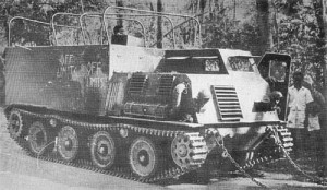 Japanese Type 1 Ho-Ki Armored Personnel Carrier
The Japanese produced a limited number of the innovativ...
Japanese Type 1 Ho-Ki Armored Personnel Carrier
The Japanese produced a limited number of the innovativ...
-
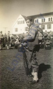 Early-War Uniform
A private photograph from 1942 showing details of the e...
Early-War Uniform
A private photograph from 1942 showing details of the e...
-
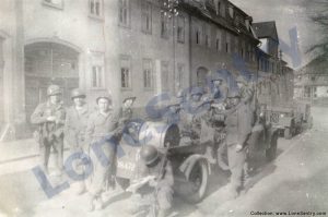 89th Infantry Division in Germany
Photographs of the U.S. Army's 89th Infantry ...
89th Infantry Division in Germany
Photographs of the U.S. Army's 89th Infantry ...
-
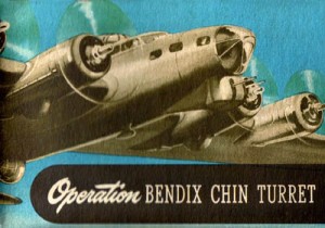 Bendix Chin Turret
Bendix manual on the Operation and Maintenance of the B...
Bendix Chin Turret
Bendix manual on the Operation and Maintenance of the B...
-
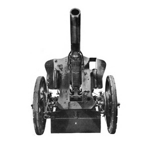 German 105-mm Howitzer
Three views of the German 105-mm howitzer (10.5 cm leFH...
German 105-mm Howitzer
Three views of the German 105-mm howitzer (10.5 cm leFH...
-
 How’s Your Sherman, Herman?
M4 Sherman Tank modification and upgrades from Army Mot...
How’s Your Sherman, Herman?
M4 Sherman Tank modification and upgrades from Army Mot...
-
Category Archives: intelligence reports
Bachem Ba 349 Natter
A report on the Bachem Ba 349 “Natter” rocket-powered fighter from April 1946 issue of Intelligence Bulletin: At first complacent in the face of the strategic bombing threat, the Germans in 1943 became fearful, then frantic. They were willing to … Continue reading
Captured Panzer II and Sd.Kfz. 233 in Tunisia
American forces in Tunisia captured immense quantities of German equipment in North Africa including this Panzer II light tank and German Sd.Kfz. 233 armored car featured in the Recognition Journal, May 1944. ORIGINAL CAPTION: U.S. Rangers round up enemy equipment at … Continue reading
Posted in armor, intelligence reports, miscellaneous, research
Tagged armored car, panzer ii, sdkfz 121, sdkfz 233, tunisia
Comments Off on Captured Panzer II and Sd.Kfz. 233 in Tunisia
Dummy Tanks in France
A report from the Intelligence Bulletin, December 1944 on the German use of dummy Panther tanks during World War II. The report includes two photographs of a dummy tank encountered in France in 1944. DUMMY TANKS Although German use of … Continue reading
Posted in armor, intelligence reports, publications, weapons
Tagged 1944, camouflage, dummy tanks, france, normandy
Comments Off on Dummy Tanks in France
Captured German Equipment
Wartime U.S. Army Signal Corp photographs of captured German equipment from 1944-1945 issues of the U.S. military training magazine Coastal Artillery with original captions. A Mark V, La Gleize
Posted in armor, artillery, intelligence reports, photos, weapons
Tagged captured, equipment, flak, heavy artillery
Comments Off on Captured German Equipment
Captured Panzer IIIs
U.S. War Department’s Tactical and Technical Trends (No. 32, August 26, 1943) featured these photographs of a pair of German Panzer III tanks captured in North Africa.
Posted in armor, combat reports, intelligence reports, publications, weapons
Tagged armor, panzer, panzer iii
Comments Off on Captured Panzer IIIs
90-mm vs. Panther Armor
The U.S. Ordnance Department published a handbook on the 90-mm M3 Gun which included the following photographs demonstrating the effectiveness of the 90-mm Hyper-Velocity Armor-Piercing Shot T30E16 and 90-mm Armor Piercing Shot T33 against the armor of the German Panther … Continue reading
V-2 rocket Support Vehicles
The April 1946 issue of the U.S. Intelligence Bulletin contained a report on German V-2 rocket launching battery support vehicles and equipment, which included highly-specialized trucks, halftracks, and trailers including the Meillerwagen trailer and the Brennstand launch platform. Source: “Guided … Continue reading
9-mm Luger Pistol M1908
The following report on the German Luger Pistole Parabellum 1908 was published in Foreign Military Weapons and Equipment, Vol. III, Infantry Weapons, Pamphlet No. 30-7-4, Department of the Army, 1954. 9-mm Luger Pistol M1908 (PISTOLE 08 or P-08) The … Continue reading
Intelligence Cartoon
Posted in intelligence reports, miscellaneous
Tagged cartoon, drawing, humor, intelligence
Comments Off on Intelligence Cartoon
Japanese Plane Names Are Given
Japanese Plane Names Are Given Navy, Army Adopt Title Listing The Navy and Army have adopted an official list of designations for Japanese military planes. Fighters carry men’s names, bombers are named after women, as are flying boats, while reconnaissance … Continue reading
Posted in aircraft, intelligence reports, miscellaneous
Tagged aircraft, japanese, names, nicknames
Comments Off on Japanese Plane Names Are Given