-

-
Popular Posts
-
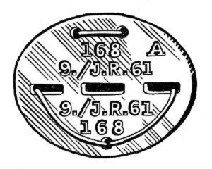 Erkennungsmarke (German Dog Tag)
From Handbook on German Army Identification, U.S. Milit...
Erkennungsmarke (German Dog Tag)
From Handbook on German Army Identification, U.S. Milit...
-
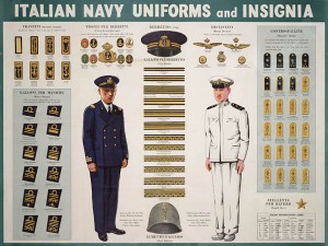 Italian Navy Uniforms and Insignia
:
CON...
Italian Navy Uniforms and Insignia
Italian Navy Uniforms and Insignia:
CON...
-
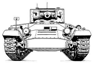 Valentine Tank Illustrations
Front and side views of the Valentine Tank (officially...
Valentine Tank Illustrations
Front and side views of the Valentine Tank (officially...
-
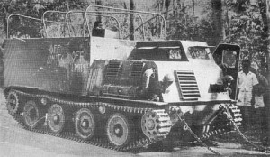 Japanese Type 1 Ho-Ki Armored Personnel Carrier
The Japanese produced a limited number of the innovativ...
Japanese Type 1 Ho-Ki Armored Personnel Carrier
The Japanese produced a limited number of the innovativ...
-
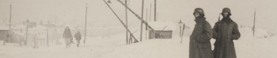
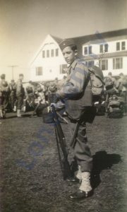 Early-War Uniform
A private photograph from 1942 showing details of the e...
Early-War Uniform
A private photograph from 1942 showing details of the e...
-
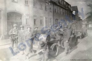 89th Infantry Division in Germany
Photographs of the U.S. Army's 89th Infantry ...
89th Infantry Division in Germany
Photographs of the U.S. Army's 89th Infantry ...
-
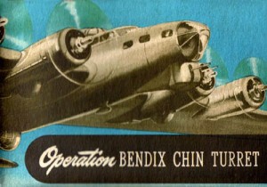 Bendix Chin Turret
Bendix manual on the Operation and Maintenance of the B...
Bendix Chin Turret
Bendix manual on the Operation and Maintenance of the B...
-
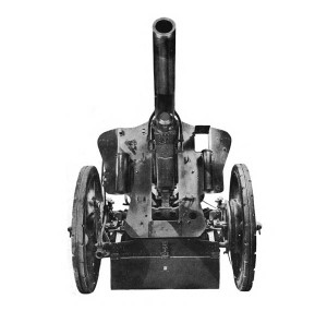 German 105-mm Howitzer
Three views of the German 105-mm howitzer (10.5 cm leFH...
German 105-mm Howitzer
Three views of the German 105-mm howitzer (10.5 cm leFH...
-
 How’s Your Sherman, Herman?
M4 Sherman Tank modification and upgrades from Army Mot...
How’s Your Sherman, Herman?
M4 Sherman Tank modification and upgrades from Army Mot...
-
Tag Archives: gun
Naval 3-Inch Mark 21 Mount
Left and right-side views of the Mark 21 mount for the 3-inch/50 cal. naval gun from Naval Ordnance and Gunnery, NAVPERS 16116, Bureau of Naval Personnel, Training Division, May 1944.
M1 57mm Anti-tank Gun Kit
Riich.Models has announced a new 1/35th-scale WWII anti-tank gun release: RV 35020: U.S. M1 57mm Anti-tank Gun on M2 carriage (Late Version). The M1 served as the standard towed anti-tank gun of the U.S. infantry divisions and over 10,000 guns were … Continue reading
Posted in scale models
Tagged 57mm, antitank, carriage, gun, M1, riich models
Comments Off on M1 57mm Anti-tank Gun Kit
Mark 24 Naval Gun Mount
Illustration of the Mark 24 3″/50 cal. naval gun mount from: Naval Ordnance and Gunnery, NAVPERS 16116, Bureau of Naval Personnel, Training Division, May 1944.
40-mm Twin Gun Assembly
40-mm Twin Gun Assembly (Source: Naval Ordnance and Gunnery, NAVPERS 16116, Bureau of Naval Personnel, Training Division, May 1944.).
5-Inch Naval Gun Turret
An interesting cutaway drawing of the Mark 12 5″/38 caliber U.S. naval gun. (Source: Naval Ordnance and Gunnery, NAVPERS 16116, Bureau of Naval Personnel, Training Division, May 1944.)
9-mm Walther Pistol M1938
Brief article on the Walther P38 semi-automatic pistol from Foreign Military Weapons and Equipment, Vol. III, Infantry Weapons, Pamphlet No. 30-7-4, Department of the Army, 1954. 9-mm Walther Pistol M1938 (PISTOLE 38 or P-38) This weapon was steadily replacing the … Continue reading
Dragon 1:72 88mm Flak 37
New 1/72nd-scale 88mm Flak 37 announcement from Dragon Models: #60634: 88mm FlaK 37, Eastern Front 1942-43.
Posted in scale models
Tagged 1/72nd, 88mm, antiaircraft, cannon, dragon, flak 37, gun
Comments Off on Dragon 1:72 88mm Flak 37
M1895 Mannlicher Rifle
8-mm M1895 Mannlicher Rifle (8-mm ÖSTERREICHISCHES REPETIER-GEWEHR M95) This weapon, the most widely used of all the Mannlicher rifles, was the standard Austro-Hungarian rifle of World War I, and huge quantities were surrendered to Italy under provisions of the Peace … Continue reading
Machine Gun Turrets
Introduction to aircraft machine gun turrets from the WWII manual Index of Aeronautical Equipment with Navy and British Equivalents: Volume 5, Armament, March 1944. MACHINE GUN TURRETS (LOCAL CONTROL TYPES) The primary function of a machine gun turret is to … Continue reading
Zvezda British 6 pdr Anti-Tank Gun
New 1/35th-scale kit from Zvezda of the British Anti-Tank Gun QF 6-PDR MK-II (Item No. 3518).