
-

-
Popular Posts
-
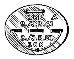 Erkennungsmarke (German Dog Tag)
From Handbook on German Army Identification, U.S. Milit...
Erkennungsmarke (German Dog Tag)
From Handbook on German Army Identification, U.S. Milit...
-
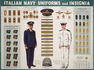 Italian Navy Uniforms and Insignia
:
CON...
Italian Navy Uniforms and Insignia
Italian Navy Uniforms and Insignia:
CON...
-
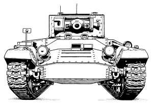 Valentine Tank Illustrations
Front and side views of the Valentine Tank (officially...
Valentine Tank Illustrations
Front and side views of the Valentine Tank (officially...
-
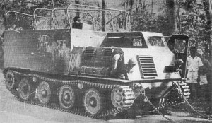 Japanese Type 1 Ho-Ki Armored Personnel Carrier
The Japanese produced a limited number of the innovativ...
Japanese Type 1 Ho-Ki Armored Personnel Carrier
The Japanese produced a limited number of the innovativ...
-
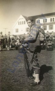 Early-War Uniform
A private photograph from 1942 showing details of the e...
Early-War Uniform
A private photograph from 1942 showing details of the e...
-
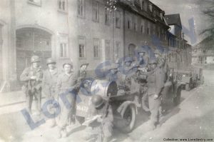 89th Infantry Division in Germany
Photographs of the U.S. Army's 89th Infantry ...
89th Infantry Division in Germany
Photographs of the U.S. Army's 89th Infantry ...
-
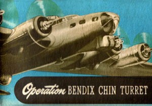 Bendix Chin Turret
Bendix manual on the Operation and Maintenance of the B...
Bendix Chin Turret
Bendix manual on the Operation and Maintenance of the B...
-
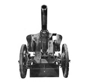 German 105-mm Howitzer
Three views of the German 105-mm howitzer (10.5 cm leFH...
German 105-mm Howitzer
Three views of the German 105-mm howitzer (10.5 cm leFH...
-
 How’s Your Sherman, Herman?
M4 Sherman Tank modification and upgrades from Army Mot...
How’s Your Sherman, Herman?
M4 Sherman Tank modification and upgrades from Army Mot...
-
Tag Archives: weapons
M39 .50 Cal. Pedestal Mount
Illustration of the M39 pedestal mount for the .50 caliber machine gun. (Source: TM 9-230: Machine Gun Mounts for Boats, War Department Technical Manual, October 1943.)
Posted in miscellaneous, navy, research, weapons
Tagged .50 cal, M39, machine gun, mount, pedestal, weapons
Comments Off on M39 .50 Cal. Pedestal Mount
Mark 24 Naval Gun Mount
Illustration of the Mark 24 3″/50 cal. naval gun mount from: Naval Ordnance and Gunnery, NAVPERS 16116, Bureau of Naval Personnel, Training Division, May 1944.
Head Control for Hull Machine Gun
Unique head control for the hull machine gun in the Panzer III. (Source: Preliminary Report No. 5, Pz Kw III, School of Tank Technology, September 1942.)
Posted in miscellaneous, research, weapons
Tagged control, head, hull, machine gun, panzer iii, weapons
Comments Off on Head Control for Hull Machine Gun
WWII British & Commonwealth Weapon Sets
New 1/35th-scale WWII weapons releases from Riich.Models: RE 30010: WWII British & Commonwealth Weapon Set A and RE 30011: WWII British & Commonwealth Weapon Set B. The two sets include a variety of WWII-era machine guns, mortars, rifles, and other small arms.
Posted in scale models
Tagged 1/35th, british, commonwealth, riich models, weapons
Comments Off on WWII British & Commonwealth Weapon Sets
Walther PP & PPK Police Pistols
The following report on the Walther PP & PPK Pistols was published in Foreign Military Weapons and Equipment, Vol. III, Infantry Weapons, Pamphlet No. 30-7-4, Department of the Army, 1954. 7.65-mm Walther Pistols Model PP and PPK (WALTHER-POLIZEI-PISTOLEN W.PP & PPK) … Continue reading
Naval Twin 5-Inch Turret
Details of the twin mount 5-inch/38 cal. naval gun from Naval Ordnance and Gunnery, NAVPERS 16116, Bureau of Naval Personnel, Training Division, May 1944.)
Sauer Pistol M1938
The following report on the Sauer Pistol M1938 was published in Foreign Military Weapons and Equipment, Vol. III, Infantry Weapons, Pamphlet No. 30-7-4, Department of the Army, 1954. 7.65-mm Sauer Pistol M1938 (7.65-mm SAUER PISTOLE, MODEL 1938) The Sauer … Continue reading
MP 34 Bergmann Submachine Gun
The following report on the MP 34 9-mm Bergmann Submachine Gun was published in Foreign Military Weapons and Equipment, Vol. III, Infantry Weapons, Pamphlet No. 30-7-4, Department of the Army, 1954. 9-mm Submachine Gun MP 34/I (Bergmann) (MASCHINENPISTOLE MP 34) This … Continue reading
12.8cm Kanone (K 81/2) Model Kit
ACE Models has announced the release of the 1/72nd-scale 12.8cm Kanone (K 81/2) PaK 44.
40mm Twin Mount and Crew
40mm twin mount and operating crew, from: Naval Ordnance and Gunnery, NAVPERS 16116, Bureau of Naval Personnel, Training Division, May 1944.