-

-
Popular Posts
-
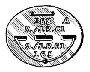 Erkennungsmarke (German Dog Tag)
From Handbook on German Army Identification, U.S. Milit...
Erkennungsmarke (German Dog Tag)
From Handbook on German Army Identification, U.S. Milit...
-
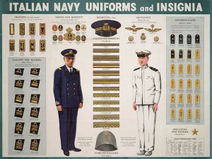 Italian Navy Uniforms and Insignia
:
CON...
Italian Navy Uniforms and Insignia
Italian Navy Uniforms and Insignia:
CON...
-
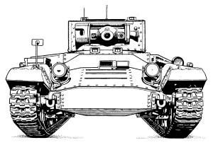 Valentine Tank Illustrations
Front and side views of the Valentine Tank (officially...
Valentine Tank Illustrations
Front and side views of the Valentine Tank (officially...
-
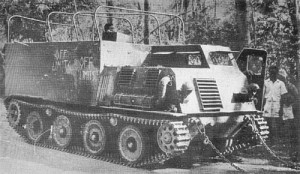 Japanese Type 1 Ho-Ki Armored Personnel Carrier
The Japanese produced a limited number of the innovativ...
Japanese Type 1 Ho-Ki Armored Personnel Carrier
The Japanese produced a limited number of the innovativ...
-
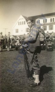 Early-War Uniform
A private photograph from 1942 showing details of the e...
Early-War Uniform
A private photograph from 1942 showing details of the e...
-
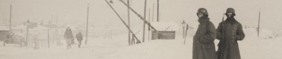
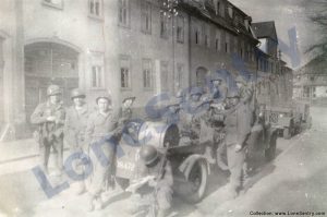 89th Infantry Division in Germany
Photographs of the U.S. Army's 89th Infantry ...
89th Infantry Division in Germany
Photographs of the U.S. Army's 89th Infantry ...
-
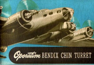 Bendix Chin Turret
Bendix manual on the Operation and Maintenance of the B...
Bendix Chin Turret
Bendix manual on the Operation and Maintenance of the B...
-
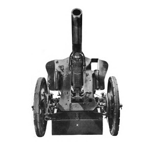 German 105-mm Howitzer
Three views of the German 105-mm howitzer (10.5 cm leFH...
German 105-mm Howitzer
Three views of the German 105-mm howitzer (10.5 cm leFH...
-
 How’s Your Sherman, Herman?
M4 Sherman Tank modification and upgrades from Army Mot...
How’s Your Sherman, Herman?
M4 Sherman Tank modification and upgrades from Army Mot...
-
Category Archives: research
Valentine Tank Bogie Wheels
Diagram of Valentine tank bogie wheels from the WW2 Russian manual.
M26 Armored Tractor
Diagrams of the M26 armored tractor from TM 9-767: 40-Ton Tank Transporter Truck-Trailer M25, War Department Technical Manual, U.S. War Department, February 1944. The M25 Tank Transporter, nicknamed the “Dragon Wagon,” was a heavy tank transporter and tank recovery vehicle … Continue reading
Posted in armor, miscellaneous, publications, research
Tagged 6x6, armored, dragon wagon, M26, tractor, trailer, transporter, truck
Comments Off on M26 Armored Tractor
P-61 Black Widow Cockpit
P-61 Black Widow cockpit instrument diagrams from the Pilot Training Manual for the Black Widow, P-61, Office of Assistant Chief of Air Staff Training, Headquarters AAF, Washington, D.C. Controls, Switches, Instruments (Front Panel) 1. Remote compass 2. Airspeed indicator 3. … Continue reading
Posted in aircraft, publications, research
Tagged black widow, cockpit, instrument panel, night fighter, P-61, pilot
Comments Off on P-61 Black Widow Cockpit
Short-Field Takeoffs in the P-61
Instructions for short-field takeoffs in the P-61 Black Widow reproduced from: Pilot Training Manual for the Black Widow, P-61, Office of Assistant Chief of Air Staff Training, Headquarters AAF, Washington, D.C. SHORT-FIELD TAKEOFFS Suppose you are on a field pitted … Continue reading
Posted in aircraft, publications, research
Tagged black widow, obstacles, P-61, runway, short-field, takeoff
1 Comment
M46 Twin MG Pedestal Mount
Illustration of the M46 pedestal mount for twin water-cooled .50 caliber machine guns. (Source: TM 9-230: Machine Gun Mounts for Boats, War Department Technical Manual, October 1943.)
12-Inch Mortar M1912
Description and characteristics of the 12-inch Mortar M1912 from TM 9-458: 12-inch Mortar M1912 Mounted on 12-inch Mortar Carriage M1896MIII, U.S. War Department Technical Manual, Washington, D.C., August 1942. 12-inch Mortar M1912 Mounted on 12-inch Mortar Carriage M1896MIII Characteristics. These 12-inch … Continue reading
Buckingham I Aircraft Recognition
Buckingham I aircraft recognition from “Antiaircraft Artillery Notes,” No. 6, November 28, 1944. Subject: Aircraft Recognition Source: AA Section, Headquarters, Twelfth Army Group. a. A new type medium bomber, the BUCKINGHAM I, is just becoming operational with the RAF. All AAA gunners in … Continue reading
Posted in aircraft, publications, research, training
Tagged AAA, Bristol, Buckingham, recognition, Type 163
Comments Off on Buckingham I Aircraft Recognition
M39 .50 Cal. Pedestal Mount
Illustration of the M39 pedestal mount for the .50 caliber machine gun. (Source: TM 9-230: Machine Gun Mounts for Boats, War Department Technical Manual, October 1943.)
Posted in miscellaneous, navy, research, weapons
Tagged .50 cal, M39, machine gun, mount, pedestal, weapons
Comments Off on M39 .50 Cal. Pedestal Mount
M25 40-ton Tank Transporter Truck-Trailer
Description and performance data for the M26 armored tractor from TM 9-767: 40-Ton Tank Transporter Truck-Trailer M25, War Department Technical Manual, U.S. War Department, February 1944. The M25 Tank Transporter, nicknamed the “Dragon Wagon,” was a heavy tank transporter and … Continue reading
Posted in armor, publications, research
Tagged data, description, dragon wagon, M25, tank, tractor, trailer, transporter
Comments Off on M25 40-ton Tank Transporter Truck-Trailer
Night Binoculars for the P-61 Pilot
Night binoculars for the P-61 Black Widow night fighter as described in the Pilot Training Manual for the Black Widow, P-61, Office of Assistant Chief of Air Staff Training, Headquarters AAF, Washington, D.C. The night binoculars combined 5.8 power night glasses with … Continue reading
Posted in aircraft, research
Tagged binoculars, black widow, gunsight, night vision, P-61
Comments Off on Night Binoculars for the P-61 Pilot