
-

-
Popular Posts
-
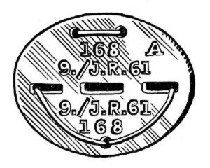 Erkennungsmarke (German Dog Tag)
From Handbook on German Army Identification, U.S. Milit...
Erkennungsmarke (German Dog Tag)
From Handbook on German Army Identification, U.S. Milit...
-
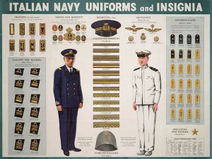 Italian Navy Uniforms and Insignia
:
CON...
Italian Navy Uniforms and Insignia
Italian Navy Uniforms and Insignia:
CON...
-
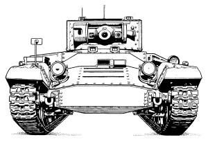 Valentine Tank Illustrations
Front and side views of the Valentine Tank (officially...
Valentine Tank Illustrations
Front and side views of the Valentine Tank (officially...
-
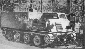 Japanese Type 1 Ho-Ki Armored Personnel Carrier
The Japanese produced a limited number of the innovativ...
Japanese Type 1 Ho-Ki Armored Personnel Carrier
The Japanese produced a limited number of the innovativ...
-
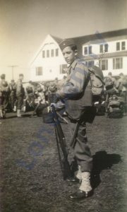 Early-War Uniform
A private photograph from 1942 showing details of the e...
Early-War Uniform
A private photograph from 1942 showing details of the e...
-
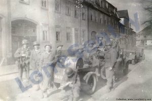 89th Infantry Division in Germany
Photographs of the U.S. Army's 89th Infantry ...
89th Infantry Division in Germany
Photographs of the U.S. Army's 89th Infantry ...
-
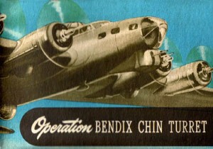 Bendix Chin Turret
Bendix manual on the Operation and Maintenance of the B...
Bendix Chin Turret
Bendix manual on the Operation and Maintenance of the B...
-
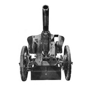 German 105-mm Howitzer
Three views of the German 105-mm howitzer (10.5 cm leFH...
German 105-mm Howitzer
Three views of the German 105-mm howitzer (10.5 cm leFH...
-
 How’s Your Sherman, Herman?
M4 Sherman Tank modification and upgrades from Army Mot...
How’s Your Sherman, Herman?
M4 Sherman Tank modification and upgrades from Army Mot...
-
Tag Archives: artillery
155-mm Gun M2
Data pertaining to the 155-mm gun M2, the carriage M1 or M1A1, the 155-mm gun mount M13 (T14), and the limbers M2 and M5. All data from the WWII U.S. War Department Technical Manual TM 9-350: 155-mm Gun M2; Carriage … Continue reading
German 105-mm Howitzer
Three views of the German 105-mm howitzer (10.5 cm leFH 18, leichte FeldHaubitze) from the U.S. War Department technical manual TM E9-325A: German 105-mm Howitzer Materiel, June 1944.
Posted in artillery, intelligence reports, miscellaneous, publications, weapons
Tagged 105mm, artillery, german, howitzer, leFH 18, manual, technical manual, weapons
Comments Off on German 105-mm Howitzer
Demolition of the 155-mm gun M2
Instruction for demolition of the 155-mm gun M2 from the WWII U.S. War Department Technical Manual TM 9-350: 155-mm Gun M2; Carriage M1 and M1A1, Gun Mount M13; Heavy Carriage Limber M2 and M5; and Firing Platform M1, May 1945. … Continue reading
155-mm Gun on Gun Motor Carriage M40
Two views of the U.S. 155-mm Gun on Gun Motor Carriage M40 from TM 9-350, the Technical Manual on the 155-mm Gun M2 printed in 1945.
WWII 105mm Howitzer M2A1 from AFV Club
Further artwork and details have been released by AFV Club on their upcoming 1/35th scale release of the U.S. WWII 105mm Howitzer M2A1 & Carriage (Kit No. AF 35160).
Posted in artillery, scale models
Tagged 105mm, afv club, artillery, howitzer, scale models
1 Comment
OP and CP Security
Observation post and command post security from Combat Lessons, No. 7: OP and CP Security Even at this late date, needless casualties, delays, and expenditures of effort are being caused by breaches of OP and CP security rules. The inevitable results … Continue reading
Posted in artillery, combat reports, training
Tagged artillery, combat lessons, command post, CP, observation post, OP
1 Comment
Panzerbeobachtungswagen III
Panzerbeobachtungswagen III (Pz Beob Wg III) were German armored, fully-tracked artillery observation vehicles developed on obsolete PzKpfw. III chassis. The hull machine gun and main armament were removed to allow more interior space for radios and equipment. A single machine … Continue reading
Posted in armor
Tagged armor, artillery, observation, panzer, panzer iii, panzerbeobachtungswagen
1 Comment
120mm Granatwerfer 42 Mortar
U.S. troops demonstrate a captured Granatwerfer 42 (12cm GrW 42) German heavy mortar on the First Army Front in Echtz, near Duren, Germany.
Artillery Against Siegfried Line Pillboxes
The following combat report by the 258th Field Artillery Battalion described the effect of short-range 155-mm artillery fire against the pillboxes of the Siegfried Line. HEADQUARTERS, 258TH FIELD ARTILLERY BATTALION APO 230, U.S. Army 5 October 1944 SUBJECT: Destruction of … Continue reading
Japanese Rockets and Launchers
The following U.S. intelligence report on Japanese spin-stabilized rockets and launchers was published in Enemy on Luzon: An Intelligence Summary: ARMY 20-CM SPIN STABILIZED ROCKET AND TYPE 4 LAUNCHER: Several of these projectiles, the first Army rockets recovered, and the … Continue reading
Posted in artillery, intelligence reports, weapons
Tagged artillery, intelligence reports, japanese, luzon, rocket
2 Comments