-

-
Popular Posts
-
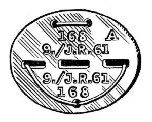 Erkennungsmarke (German Dog Tag)
From Handbook on German Army Identification, U.S. Milit...
Erkennungsmarke (German Dog Tag)
From Handbook on German Army Identification, U.S. Milit...
-
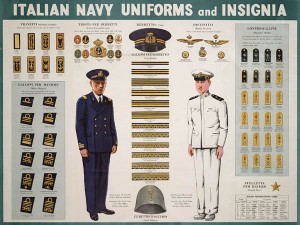 Italian Navy Uniforms and Insignia
:
CON...
Italian Navy Uniforms and Insignia
Italian Navy Uniforms and Insignia:
CON...
-
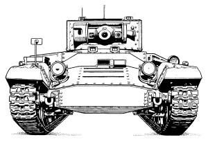 Valentine Tank Illustrations
Front and side views of the Valentine Tank (officially...
Valentine Tank Illustrations
Front and side views of the Valentine Tank (officially...
-
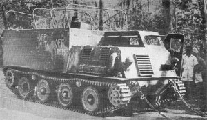 Japanese Type 1 Ho-Ki Armored Personnel Carrier
The Japanese produced a limited number of the innovativ...
Japanese Type 1 Ho-Ki Armored Personnel Carrier
The Japanese produced a limited number of the innovativ...
-
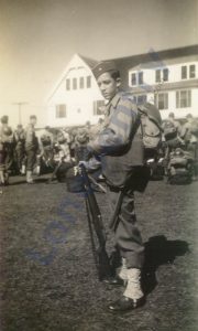 Early-War Uniform
A private photograph from 1942 showing details of the e...
Early-War Uniform
A private photograph from 1942 showing details of the e...
-
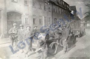 89th Infantry Division in Germany
Photographs of the U.S. Army's 89th Infantry ...
89th Infantry Division in Germany
Photographs of the U.S. Army's 89th Infantry ...
-
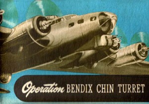 Bendix Chin Turret
Bendix manual on the Operation and Maintenance of the B...
Bendix Chin Turret
Bendix manual on the Operation and Maintenance of the B...
-
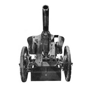 German 105-mm Howitzer
Three views of the German 105-mm howitzer (10.5 cm leFH...
German 105-mm Howitzer
Three views of the German 105-mm howitzer (10.5 cm leFH...
-
 How’s Your Sherman, Herman?
M4 Sherman Tank modification and upgrades from Army Mot...
How’s Your Sherman, Herman?
M4 Sherman Tank modification and upgrades from Army Mot...
-
Category Archives: weapons
995th Field Artillery Battalion #1
8-inch howitzers of the 995th Field Artillery Battalion. See also: 995th Field Artillery Battalion Photo Album. (Collection LoneSentry.com)
Captured Panzer IIIs
U.S. War Department’s Tactical and Technical Trends (No. 32, August 26, 1943) featured these photographs of a pair of German Panzer III tanks captured in North Africa.
Posted in armor, combat reports, intelligence reports, publications, weapons
Tagged armor, panzer, panzer iii
Comments Off on Captured Panzer IIIs
Subcaliber Gunnery Training
Subcaliber firing was used by the U.S. Army to develop a tank gunner’s accuracy, speed, and confidence without the costs and disturbance of firing the main armament. In general, the coaxial machine gun was used for the subcaliber training for … Continue reading
Posted in armor, miscellaneous, publications, research, training, weapons
Tagged gunnery, m4, sherman, subcaliber, tank, training
Comments Off on Subcaliber Gunnery Training
90-mm vs. Panther Armor
The U.S. Ordnance Department published a handbook on the 90-mm M3 Gun which included the following photographs demonstrating the effectiveness of the 90-mm Hyper-Velocity Armor-Piercing Shot T30E16 and 90-mm Armor Piercing Shot T33 against the armor of the German Panther … Continue reading
Soviet T-26 Light Tank
German troops inspect a destroyed Russian T-26 light tank, pierced behind the turret vertical armor seam.
V-2 rocket Support Vehicles
The April 1946 issue of the U.S. Intelligence Bulletin contained a report on German V-2 rocket launching battery support vehicles and equipment, which included highly-specialized trucks, halftracks, and trailers including the Meillerwagen trailer and the Brennstand launch platform. Source: “Guided … Continue reading
Helldiver Debut at Rabaul
Details of the combat debut of the U.S. Navy’s Curtiss SB2C Helldiver dive bomber at the Battle of Rabaul from Bureau of Naval Personnel Information Bulletin, February 1944. HELLDIVER The Navy’s New Dive Bomber Makes Debut In Smash at Rabaul The … Continue reading
AAA Ground Recognition Signals
The following comments from the commander of the U.S. 5th Armored Division on the proper use of ground recognition signals were published in “Antiaircraft Artillery Notes,” No. 5, November 22, 1944. Subject: Use of Ground Recognition Signals Source: AA Section, Headquarters Twelfth Army … Continue reading
Posted in aircraft, publications, research, weapons
Tagged AAA, antiaircraft, combat reports, flares, recognition, research, signals, training
Comments Off on AAA Ground Recognition Signals
M46 Twin MG Pedestal Mount
Illustration of the M46 pedestal mount for twin water-cooled .50 caliber machine guns. (Source: TM 9-230: Machine Gun Mounts for Boats, War Department Technical Manual, October 1943.)
Naval 3-Inch Mark 21 Mount
Left and right-side views of the Mark 21 mount for the 3-inch/50 cal. naval gun from Naval Ordnance and Gunnery, NAVPERS 16116, Bureau of Naval Personnel, Training Division, May 1944.