A description of Airborne Transmitting Equipment AN/APT-1 used to jam enemy radars in WWII from Graphic Survey of Radio and Radar Equipment Used by the Army Air Forces, Army Air Forces, Air Technical Service Command, Wright Field, Dayton, Ohio, February 1945:
Transmitting Equipment AN/APT-1 is an airborne transmitter used to jam enemy radars in the 95-210 mc. frequency range. This band includes most of the enemy early warning radars such as the German Freya, Hoardings and Wasserman and Japanese radars of equivalent type. The equipment employs the DINA (Direct Noise Amplification) type of transmission and may be used either as a spot jammer or as a barrage type jammer.
The carrier frequency is suppressed and all of the output power is concentrated in the side bands, affording more effective jamming coverage with less power. It will effectively screen an AN/APT-l equipped bomber to within two miles of a Freya radar.
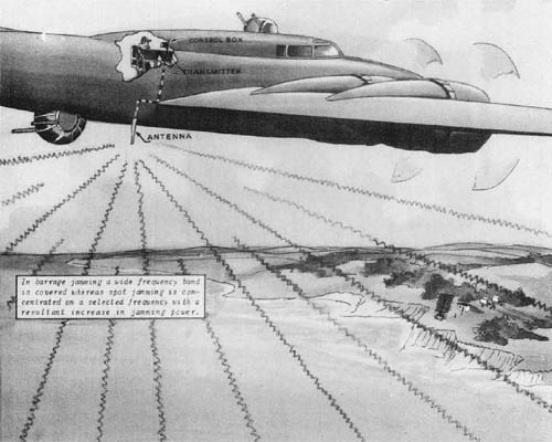
Radar Transmitting Equipment AN/APT-1 (Installed in B-17) may be used for spot or barrage jamming of enemy radars in the frequency range from 95 to 210 mc. (i.e. German Freya or Japanese equivalent types.)
For barrage jamming the equipment is adjusted to the required frequency prior to take-off, after which only the power output need be controlled.
For spot jamming the set must be tuned in flight by means of the control unit. Employing R-F Amplifier AM-14/APT or AM-18/APT the output of the equipment can be increased effectively. Two sets of three antennas are available for complete frequency coverage. All are of the quarter-wave stub type. One set is designed for vertical mounting and the other set is designed for mounting at an angle of 45 degrees.
Power is obtained from an 80/115 volt, 400-2600 c.p.s., a.c. source and a 28 volt d.c. source.
Test equipment required for the maintenance and tuning of the equipment includes Test Set I-139-A, Amplifier Alignment Unit TS-92/AP, Radio Frequency Wattmeter TS-118/AP or TS-92/AP, Pickup Assembly TS-131/AP, Test Set I-56-K and Frequency Meter TS-174/AP.
Army Supply Program requirements as of 20 November 1944 were 4,895 for the calendar year 1944 and 3,086 for 1945.
POWER INPUT 325 WATTS POWER OUTPUT 30-8 WATTS (All sideband) FREQUENCY 95-210 MC. TYPE OF SIGNAL DIRECT NOISE
TUBE COMPLEMENT NO. TYPE NO. TYPE 2 5R4GY 1 6X5GT 3 6AC7 1 931A 2 6C4 2 832* 1 6V6GT/X 1 829B* *One 829B substituted for one 832 for increased power over 95-150 Mc.
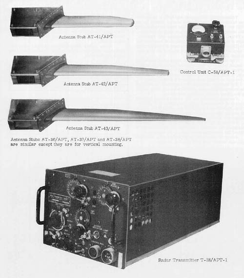
(i) Antenna Stubs AT-36/APT, AT-37/APT and AT-38/APT are similar except they are for vertical mounting. (ii) Control Unit C-58/APT-1. (iii) Radar Transmitter T-28/APT-1.
RADAR SET AN/APT-1 TOTAL WEIGHT 70 LBS. Component Nomenclature Size Weight Radar Transmitter T-28/APT-1 7 5/8″ x 10 1/8″ x 21 3/4″ 43 Lb. Control Unit C-58/APT-1 3 1/2″ x 3 1/2″ x 2 1/2″ 1 1/2 Lb. Mounting Base MT-171/U 2 1/4″ x 10 5/8″ x 22″ 3 1/4 Lb. Mounting Base MT-114/APT-1 5″ x 5″ x 3/4″ 1 1/4 Lb. Antenna Stub AT-36/APT or AT-41/APT Length 16 1/2″ 6 1/2 Lb. Antenna Stub AT-37/APT or AT-42/APT Length 22 1/2″ 6 1/2 Lb. Antenna Stub AT-38/APT or AT-43/APT Length 29″ 6 1/2 Lb. and includes plugs, adapters, and misc. cables.






Great blog. A pleasure to read.
Thanks for the info! My Father in Law worked as an engineer during WWII. They would not enlist him because his specialty was aircraft and they needed him to build/design aircraft. I have been researching a box that has the markings TS-92/AP on and wondered what it meant. This box is just an empty box he used for fishing but I could tell it was remade from something industrial and in the 40’s or 50’s, Now I have my answer so thank you.