NOTES ON ENEMY AIRCRAFT
The information contained in this summary should be transferred immediately to Informational Intelligence Summary No. 43-26, “Japanese Aircraft and Armament,” revised September 1943.
JAPAN
New Japanese Type 2 Single-Engine Fighter, TOJO
TOJO 1. Informational Intelligence Summaries No. 43-49 of 10 November and No. 43-51 of 30 November contained certain previously known details of the Type 2 single-engine fighter TOJO. A recent report has been received that includes sketches and drawings of this aircraft, these being reproduced in Fig. 6. Data supplementary to that given in the Summaries mentioned above follows:
a. Wing is constructed in six sections. It is joined by bolted-type joints at the centerline, and at points 6 1/2 ft., and 12 ft. 11 in. outboard from the centerline, the last-named being the tip attachment. Each wing, therefore, is composed of sections 6 1/2 ft., 6 ft. 5 in. and 2 ft. 8 in. long. No protective or de-icing devices are on or in wing leading edge.
Figure 6: Tojo
b. Fowler type flaps are operated hydraulically as well as the engine cowl flaps. A hand hydraulic pump is incorporated in the system as well as the engine-driven pump.
c. Cockpit is high-set over wing, with little streamlining.
d. Wheels retract hydraulically inward into wheel wells that form bulges in the wing leading edge at the fuselage.
e. Fuel tanks show evidence of attempts at self-sealing (probably similar to OSCAR, TONY and LILY). It is ineffective against U.S. .50 cal. fire. The tanks were covered with inflammable wool felt insulation. Two tanks are in each wing root, one of which measured 8 x 26 x 35 inches, which would give a capacity of about 27 1/2 U.S. gals. From the way one aircraft burned, a large fuel tank might also have been located in the fuselage.
f. Vulnerability. A short burst of .50 cal. ammunition fired into the left wing root caused one aircraft to start burning and crash. No armor plate was fitted.
g. Ammunition used was:
(1) Armor-piercing tracer–green and white band.
(2) Explosive–white band.
(3) Incendiary (new type)–dark purple band.
a. Believed to contain thermite.
(4) Two types of loading were used in groups of about twenty rounds each.
a. Group I: 1 explosive, 2 armor-piercing tracer.
b. Group II: 1 explosive, 1 armor-piercing tracer, 1 incendiary.h. A small inclosed running light is placed in each wing tip.
i. Power Plant. Although some details of the Nakajima 1450 h.p. twin-row air-cooled radial engine are contained in the previous Summaries, a consolidated report of all the details is given below.
a. Description: Conventional, compact design, 14 cylinder, twin-row, air-cooled, radial engine, incorporating a two speed mechanical type blower, hydromatic constant speed and variable pitch propeller control gearing, front and rear cam plates used for front and rear cylinder valves respectively.b. Specifications:
Cylinder bore . . . . . 5.75 in. Piston Stroke . . . . . 6.30″. Displacement . . . . . 2290 Cu. in. Reduction gear ratio . . . . . 11:16 Supercharger: . . . . . 8.64:1 Low ratio . . . . . 7.20:1 Impeller is 22 blade, diameter 12 inches, height 3 inches. Overall diameter . . . . . 48 in.
c. Pistons: Light alloy, forged and machined. Square “honey-comb” ribbing cast underneath the head and finning inside the skirt. Half-moon cutouts in piston skirt below the piston pin to allow counter weight clearance. Three compression rings and two oil rings in one groove above piston pin. One ring in groove on piston skirt. Piston weight 1.910 kg. (4.3 lbs).
d. Piston pins: Full floating type.
e. Cylinders: Steel barrel, alloy head, screwed and shrunk on. One inlet and one exhaust valve per cylinder. Two spark plugs per cylinder. Three valve springs per valve. Valves retained by split-collets. Noticeably deep finning on both barrel and head. Bore 5.75 inches.
f. Valves: Tulip-type intake valve, chrome plated. Mushroom type exhaust valve.
g. Cam gears: Double three lobe track for each row of cylinders, the front row being served by one located in front” of the engine, the rear row served by a cam behind the crankcase proper.
h. Master rod: One piece construction.
i. Reduction gears: Epicyclic spur type (Wright Pattern)
Number of teeth of Annulus gear . . . . . 66 Number of teeth on Sun gear . . . . . 30 Six planer gears with 18 teeth each Reduction ratio . . . . . 11:16
j. Thrust bearing: (Propeller) Ball thrust type.
k. Main bearing: All roller type bearings.
l. Crankcase: Conventional design, blower section, power section and nose section. Alloy, bolted together.
m. Propeller hub: Standard Hamilton v.p., c.s. type.
n. Constant speed gear: Driven from front cam ring.
o. Carburetor: Three-barrel, down-draft, low-pressure type with three cork floats.
p. General: Quality, workmanship and finish are comparable with U.S. standards. The basic design shows strong influence from Pratt Whitney with some adaptations from the Wright designs. Sound, logical engineering advancements have been made by the Japanese engineers and the fact that the cutouts in the piston make possible a longer stroke with this diameter engine is worthy of note. As no radical changes in design from previous Japanese models have been made it is felt that this engine should have dependable performance.

-

-
Popular Posts
-
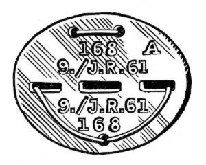 Erkennungsmarke (German Dog Tag)
From Handbook on German Army Identification, U.S. Milit...
Erkennungsmarke (German Dog Tag)
From Handbook on German Army Identification, U.S. Milit...
-
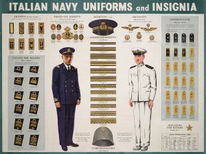 Italian Navy Uniforms and Insignia
:
CON...
Italian Navy Uniforms and Insignia
Italian Navy Uniforms and Insignia:
CON...
-
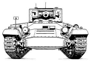 Valentine Tank Illustrations
Front and side views of the Valentine Tank (officially...
Valentine Tank Illustrations
Front and side views of the Valentine Tank (officially...
-
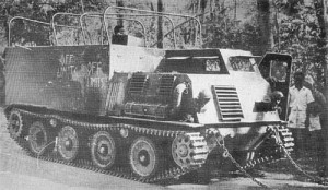 Japanese Type 1 Ho-Ki Armored Personnel Carrier
The Japanese produced a limited number of the innovativ...
Japanese Type 1 Ho-Ki Armored Personnel Carrier
The Japanese produced a limited number of the innovativ...
-
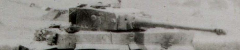
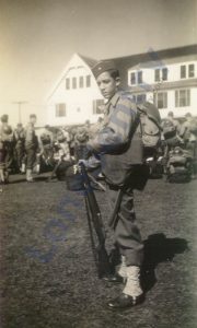 Early-War Uniform
A private photograph from 1942 showing details of the e...
Early-War Uniform
A private photograph from 1942 showing details of the e...
-
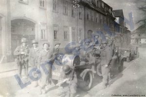 89th Infantry Division in Germany
Photographs of the U.S. Army's 89th Infantry ...
89th Infantry Division in Germany
Photographs of the U.S. Army's 89th Infantry ...
-
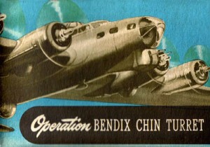 Bendix Chin Turret
Bendix manual on the Operation and Maintenance of the B...
Bendix Chin Turret
Bendix manual on the Operation and Maintenance of the B...
-
 German 105-mm Howitzer
Three views of the German 105-mm howitzer (10.5 cm leFH...
German 105-mm Howitzer
Three views of the German 105-mm howitzer (10.5 cm leFH...
-
 How’s Your Sherman, Herman?
M4 Sherman Tank modification and upgrades from Army Mot...
How’s Your Sherman, Herman?
M4 Sherman Tank modification and upgrades from Army Mot...
-
Not a bad plane, but it had no chance against Allied fighters. Definitelly better than the Oscar.