
“Battle Route of the 10th Armored Division” from the G.I. Stories booklet: Terrify and Destroy: The Story of the 10th Armored Division published by the Information and Education Division, ETOUSA in 1945.
“Battle Route of the 10th Armored Division” from the G.I. Stories booklet: Terrify and Destroy: The Story of the 10th Armored Division published by the Information and Education Division, ETOUSA in 1945.
Summary of Japanese prisoners and documents captured on Luzon from Enemy on Luzon: An Intelligence Summary:

Oat of a total of 7,297 prisoners of war captured during the entire Luzon Operation, the divisions evaluated 4,932 and actually interrogated 3,421. They issued 2,387 interrogation reports, an average of 199 per division and RCT. Here again, the personnel involved were approximately 60 officers and enlisted men. Of the 3,421 prisoners interrogated, 2,646 were Japanese, the rest being Formosans and Koreans. Ninety-four percent of the Japanese prisoners evaluated were interrogated, whereas thirty-six percent of the Formosans evaluated were interrogated….
The corps evaluated 4,166 prisoners of war, of which 1,984 were interrogated; and 604 interrogation reports were issued. This was an average of 201 interrogation reports per corps. It is to be noted that most of these prisoners came directly from the divisions and were further interrogated….
The Army Language Detachment evaluated 1,166 prisoners of war, of which 207 were interrogated; and 165 interrogation reports were issued.

Captured enemy documents were classified as follows:
New summer releases of WW2 kits from MIG Productions.
 |
Due to plentiful motorized transport, U.S. infantry rarely rode on tanks during WWII. However, U.S. infantrymen were trained on how to board and ride tanks when necessary. The field manual FM 17-40: Armored Infantry Company contained instructions for transporting armored infantry by tanks. |
ARMORED INFANTRY TRANSPORTED ON TANKS 1. PURPOSE AND SCOPE. This appendix is a guide for unit commanders in planning the training of armored infantry rifle companies in riding on tanks and tank units in transporting the armored infantry rifle companies.
2. SITUATIONS ADAPTABLE TO MOUNTING ARMORED INFANTRY ON TANKS. Three situations in which it may be desirable to transport infantry on tanks are—
a. When it is desired to avoid traffic congestion by withholding the organic vehicles of the infantry temporarily. These vehicles will follow as soon as the traffic conditions of the roads permit.
b. When the terrain is unsuitable for the organic vehicles of the armored infantry.
c. When close mutual support is desired and maximum coordination must be achieved.
3. CONSIDERATIONS AFFECTING TRANSPORTATION OF ARMORED INFANTRY ON TANKS. a. The employment of tanks for transporting armored infantry must not interfere with the primary mission of the tanks. The decision for this employment is made by the commander of the combined infantry-tank force.
b. Tactical unity of both tank and infantry organizations must be preserved to the maximum extent in all echelons of command, from the battalion down to the squad or crew.
c. Coordination and planning must be thorough and include designation of specific tanks for infantry elements, provision for guiding the infantry to the tank positions, and provision for communication both between infantry and tank commanders and within the infantry chain of command.
d. The armored infantry and tank units should have had prior training together. The infantry squad members are trained in securing themselves on the tank to safely travel over rough ground, in riding over extended periods with the minimum possible physical discomfort, and in using the protection afforded by the turret. Care must be taken by the infantry not to block the ventilator on the rear of the tank.
e. The tank commander is trained to coordinate with the infantry squad leader. The tank driver most drive carefully over rough terrain and through wooded areas to insure the safety of infantrymen on the tank deck.
f. Infantry riding on tanks will maintain continuous all-around observation for hostile air or ground action. A sector of responsibility is assigned each infantryman according to his position on the tank. One man will be designated as the air sentinel. When passing through wooded or jungle areas the air sentinel will also observe for snipers in trees, particularly to the front.
4. TRANSPORTATION OF INFANTRY NOT IN IMMEDIATE PRESENCE OF ENEMY. a. Armored infantry not in the immediate presence of the enemy may be mounted in larger groups on the tank than when tactical employment is contemplated. Distribution should be flexible in order that adjustments can be made due to vehicles being forced out of action. Tactical unity is preserved in the rifle and tank companies whenever possible.
b. Responsibility The infantry commander is responsible for the movement of infantry personnel to the tanks and the mounting thereon. The tank unit commander provides guides to conduct infantry personnel to the particular tanks which they will mount. The actual march is under the control of the tank unit commander with respect to routes, rate of march, and halts. Provision is made for rest periods, and to allow the infantry to dismount whenever fire is received from artillery or aircraft.
c. Coordination. Upon receipt of orders to transport infantry on tanks, the tank unit commander establishes liaison with the infantry unit to coordinate the planning of the movement. The liaison officer will furnish accurate information to the infantry on the number of tanks available, tank communication facilities available to the infantry, number of guides to be furnished by tank unit, and other necessary information.
d. Planning should provide for the infantry company and platoon commanders to be mounted on vehicles of corresponding tank unit commanders, thereby allowing direct communication between them and utilizing the tank unit radio net for the transmission of messages within the infantry chain of command. Where possible, the infantry company commander’s 1/4-ton truck with SCR-510 should follow the tank company commander. It will then be immediately available to the infantry commander when the company dismounts. Additional communication may be planned for the use of prearranged visual signals for mounting, dismounting, and dispersing of the infantry.
5. TACTICAL CONSIDERATIONS. a. Six men is the maximum that can conveniently ride for any distance on the rear of a medium tank. For this reason, six has been taken as the basic number for the drills prescribed herein. The tank turret will furnish partial protection for this number from frontal fire.
b. Tactical unity must be preserved to the greatest possible degree.
6. DISTRIBUTION OF INFANTRY TO TANKS. a. Assignment for mounting of an armored infantry rifle platoon on the tanks of a medium tank company is shown in figure 40.
Figure 40. Armored rifle platoon mounted on tanks of medium tank company.
b. Assignment for mounting of two armored infantry rifle platoons on a company of medium tanks is shown in figure 41. (Note. The charts show organization, not formation.)
Figure 41. Two armored rifle platoons mounted on tanks of medium tank company.
7. COORDINATION. All of the elements discussed under coordination in paragraph 4c will apply.
8. SIGNAL COMMUNICATION. Careful pre-planning must provide for communication between the tanks and infantry both when the infantry are mounted and dismounted. Tank unit radio channels should be chosen for inter-netting with the infantry and an appropriate SOI set up for the operation. External telephones installed on the rear of tanks and connected with the tank interphone system will provide communication between dismounted infantry and tank crews.
9. INSTALLATION OF HANDHOLDS. a. Rope. The installation of a rope handhold attached to the lifting hooks on the turret is a satisfactory means for the
infantrymen to hold on and maintain their position while riding on the tank. Figure 42 shows arrangement of ropes on a medium tank.Figure 42. Arrangement of ropes on medium tank, M4A1.
Figure 43. Six infantrymen mounted on medium tank, M4A1 (left view).
Figure 44. Six infantrymen mounted on medium tank, M4A1 (rear view).
Note. An armored infantry rifle company less the antitank platoon, administrative, mess, supply and maintenance sections,
and personnel with vehicles, may be mounted on two medium tank companies as follows:b. One rifle platoon is mounted as shown in figure 40 except as noted in c below.
c. Two rifle platoons are mounted as shown in figure 41 except as noted in c below.
d. The armored infantry company command section may be mounted on the tank company commander’s tank of either tank company. If mounted with the tank company carrying one rifle platoon of armored infantry, the following units are displaced:
(1) 1/2 PLAT HQ & RIFLE SQD (one officer and 5 enlisted men) from the CO’s tank to the No. 1 tank of the 3d tank platoon.
(2) 1/2 PLAT HQ & RIFLE SQD (6 enlisted men including 1 rifleman from mortar sqd) from No. 1 tank of the 3d tank platoon to the No. 2 tank of the same platoon.
e. If mounted with the tank company carrying two rifle platoons of armored infantry the following units are displaced:
(1) 1/2 PLAT HQ & RIFLE SQD (one officer and 5 enlisted men) from the CO’s tank to the No. 1 tank of the 3d tank platoon.
(2) 1/2 PLAT HQ & RIFLE SQD (6 enlisted men including 1 rifleman form mortar sqd) from No. 5 tank of the 3d tank platoon to the howitzer tank of the other tank company.
Figure 45. Drill for the mounting of armored infantry on tanks.
Figure 46. Drill for the mounting of armored infantry on tanks.
Figure 47. Drill for the mounting of armored infantry on tanks.
Figure 48. Drill for the mounting of armored infantry on tanks.
Figure 49. Drill for the mounting of armored infantry on tanks.
1:35 ’39-’45 Series: StuG. III Ausf. F/8 Late Production w/ Winter Track: 
1:35 ’39-’45 Series: 7.5cm PaK 40/4 auf RSO: 
1:35 ’39-’45 Series: Sd.Kfz. 166 Stu.Pz. IV Brummbär Early Production w/ Zimmerit: 
Part 1 covering the Kar 98k rifle, MP 40 submachine gun, Luger pistol, and stick grenade:
Part 2 covering the MG 34 machine gun, MG 42 machine gun, 8 cm mortar, and 88 mm gun:
Definition of elements of trajectory from FM 4-10: Coast Artillery Gunnery, War Department Field Manual, May 1944.
Elements of Trajectory
- 6. GENERAL. The trajectory is the path of the projectile from the muzzle of the gun to the first point of impact. The phrase, elements of the trajectory, is applied to the various features of the trajectory. (See figure.) The elements most frequently referred to are defined in the following paragraphs.
- 7. INTRINSIC ELEMENTS.
- a. Trajectory. The curve described by the center of gravity of the projectile in flight.
b. Ascending branch. That portion of the trajectory described by the projectile while rising.
c. Descending branch. That portion of the trajectory described by the projectile while falling.
d. Origin. The center of the muzzle of the piece at the instant of departure.
e. Summit. The highest point on the trajectory.
f. Level point. The point on the descending branch of the trajectory at the same altitude as the origin.
g. Base of the trajectory. The straight line between the origin and the level point.
h. Maximum ordinate. Difference in altitude between the origin and the summit.
- 8. INITIAL ELEMENTS.
- a. Line of elevation. The prolongation of the axis of the bore when the piece is set.
b. Line of departure. The prolongation of the axis of the bore as the projectile leaves the muzzle of the gun. It is tangent to the trajectory at its origin.
c. Line of site. The straight line between the origin of the trajectory and the target.
d. Plane of fire. The vertical plane containing the line of elevation.
e. Plane of departure. The vertical plane containing the line of departure.
f. Angle of elevation or elevation. The angle between the line of site and the line of elevation.
g. Angle of departure. The angle between the line of site and the line of departure.
h. Angle of site (ε). The angle between the line of site and the base of the trajectory.
i. Quadrant angle of elevation (φ) or quadrant elevation. The angle between the horizontal and the line of elevation.
j. Quadrant angle of departure (φ’). The angle between the horizontal and the line of departure.
k. Lateral jump. The horizontal angle between the plane of fire and the plane of departure.
l. Vertical jump. The difference between the angle of elevation and the angle of departure. It is positive if the angle of departure is greater than the angle of elevation.
- 9. TERMINAL ELEMENTS.
- a. Point of impact. The point where the projectile first strikes an object.
b. Line of fall. The line tangent to the trajectory at the level point.
c. Angle of fall (ω). The angle between the line of fall and the base of the trajectory.
- 10. OTHER ELEMENTS.
- a. Muzzle velocity (MV or V). Muzzle velocity or initial velocity is the velocity with which the projectile is assumed to leave the muzzle of the gun. It is the velocity of the projectile, measured at a distance from the muzzle, corrected for the theoretical loss in velocity during the travel from the origin of the trajectory to the point of measurement, considering that during that travel the projectile has been acted upon only by air resistance and gravity.
b. Remaining velocity. The remaining velocity at any point of the trajectory is the actual velocity at that point.
c. Terminal velocity (Vω). The remaining velocity at the level point.
d. Time of flight (t). The elapsed time from the instant the projectile leaves the muzzle to the instant of impact or to the instant of burst.
e. Range. The horizontal distance between two points, such as from the gun or directing point of a battery to the target.
f. Drift. The divergence of a projectile, due to its rotation and the resistance of air, from the plane of departure. It is usually expressed in angular units.
The following simplified Italian ship silhouettes show the profiles and relative sizes of the various classes of battleships, cruisers, and destroyers in the Italian Navy in WWII. The silhouettes are taken from the U.S. Navy manual FM 30-50: Recognition Pictorial Manual of Naval Vessels.

From top to bottom, ships shown are
Source: FM 30-50: Recognition Pictorial Manual of Naval Vessels, U.S. Navy Department, September 1943.

“Thru France with the 2nd” from the G.I. Stories booklet: From D + 1 to 105: The Story of the 2nd Infantry Division published by the Information and Education Division, ETOUSA in 1944-45.
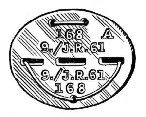 Erkennungsmarke (German Dog Tag)
From Handbook on German Army Identification, U.S. Milit...
Erkennungsmarke (German Dog Tag)
From Handbook on German Army Identification, U.S. Milit...
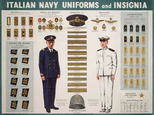 Italian Navy Uniforms and Insignia
:
CON...
Italian Navy Uniforms and Insignia
Italian Navy Uniforms and Insignia:
CON...
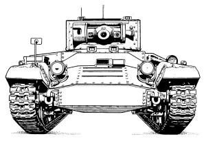 Valentine Tank Illustrations
Front and side views of the Valentine Tank (officially...
Valentine Tank Illustrations
Front and side views of the Valentine Tank (officially...
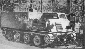 Japanese Type 1 Ho-Ki Armored Personnel Carrier
The Japanese produced a limited number of the innovativ...
Japanese Type 1 Ho-Ki Armored Personnel Carrier
The Japanese produced a limited number of the innovativ...
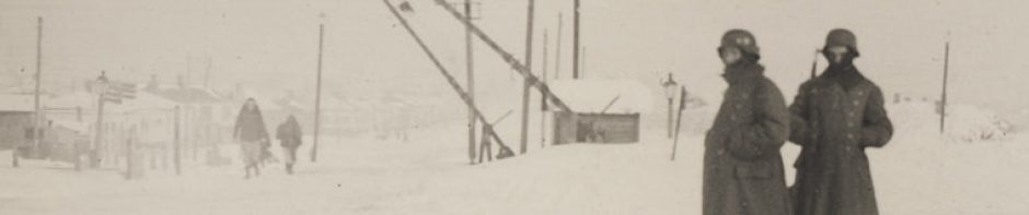
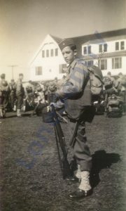 Early-War Uniform
A private photograph from 1942 showing details of the e...
Early-War Uniform
A private photograph from 1942 showing details of the e...
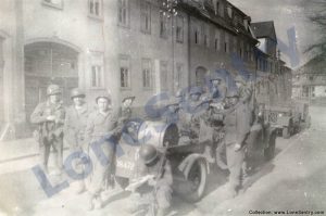 89th Infantry Division in Germany
Photographs of the U.S. Army's 89th Infantry ...
89th Infantry Division in Germany
Photographs of the U.S. Army's 89th Infantry ...
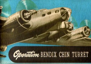 Bendix Chin Turret
Bendix manual on the Operation and Maintenance of the B...
Bendix Chin Turret
Bendix manual on the Operation and Maintenance of the B...
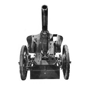 German 105-mm Howitzer
Three views of the German 105-mm howitzer (10.5 cm leFH...
German 105-mm Howitzer
Three views of the German 105-mm howitzer (10.5 cm leFH...
 How’s Your Sherman, Herman?
M4 Sherman Tank modification and upgrades from Army Mot...
How’s Your Sherman, Herman?
M4 Sherman Tank modification and upgrades from Army Mot...


