Categories
German

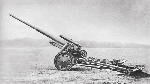
21 cm Mrs. mit Mrs. Laf. 18: Heavy Howitzer

21 cm Morserlafette 18 Heavy Howitzer

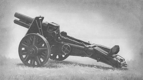
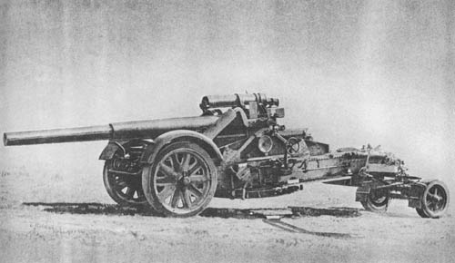
The 21 cm Morserlafette 18 is the standard heavy howitzer in use by German troops. The piece comprises a loose barrel, half jacket, and breech ring. A lug on the collar of the barrel secures it to the breech ring; ring and jacket are fastened together by a key which fits into a key way in the latter. The ring, jacket, and barrel are clamped together by a securing ring at the front of the jacket.

During recoil, the piece is supported by a pair of rollers below the jacket and another pair under the rear of the breech ring. A bracket at the top of the breech ring receives the piston rod, and a lug on its lower face receives the buffer piston rod.

The breechblock is of the horizontal sliding block type. On the rear face of the breech ring is a lever which operates (a) a plunger in a vertical boring in the bottom of the breech opening, and (b) a catch engaging a slot in the buffer nut interlocking the breech mechanism.

The carriage is interchangeable with that of the 17 cm K. mit Mrs. Laf. 18, with the exception of the following points: the safety limit of recoil of the upper mounting is 58.27 inches, whereas in the case of the 17 cm K. mit Mrs. Laf. 18 it is 56.30 inches; and the air pressure in the compensators is 464 lb./sq. in. against 626 lb./sq. in. in the case of the 17 cm K. The latest model of the 21 cm and 17 cm Mrs. Laf. 18 carriage is equipped with a pivot platform attached to a supporting frame situated near the center of the lower carriage body, which allows complete and continuous 360° traverse.

SPECIFICATIONS

Caliber         21 cm (8.27 ins.)
Weight of gun in action 18.5 tons
Weight of piece 5.79 tons
Length of howitzer (travelling) 41 ft., 2 ins.
Length of bore 17 ft., 3 ins.
Length of chamber 25.31 ins.
Number of grooves 64
Rate of fire 1 rd./min.
Muzzle velocity 1,854 f/s
Range (maximum) 18,263 yds.
Elevation 70°
Traverse 16° (360° with the pivot platform)
Ammunition High-explosive (wt. 249 lbs.)
  Anti-concrete shell (wt. 268 lbs.)

German: p. 101

Categories
German

8 cm s. Gr. W. 34: Heavy Mortar

8 cm s. Gr. W. 34: Heavy Mortar (WW2)

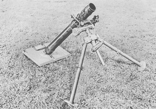
The German 8.1 cm heavy mortar, first manufactured in 1934, is of conventional design, consisting of a tube, base cap, and firing-pin mechanism. Wall thickness of the tube or barrel tapers from 0.288 inch at the base cap to 0.190 inch; a collar at the muzzle slightly increases the wall thickness at that point. A leather-covered handle attached to the collar clamp near the muzzle is used apparently to change elevations when the tube is hot. The firing pin mechanism can be adjusted for two positions. In the “On” position, the pin protrudes into the tube the correct length for firing; in the “Safe” position, the firing-pin head is retracted, permitting greater safety in unloading the mortar in the event of a misfire or other malfunction. The change in setting is readily made by means of an adjuster located on the side of the base ring. The mortar is supported by a bipod and base plate.

The bipod includes cross-leveling, elevating and traversing mechanisms. The legs, and all other nonsliding parts, are made of light white metal. These legs, which have spikes and feet attached to the bottom, are adjusted to any one of six positions by a lever and held in place by locking gears. General construction of the bipod is sturdy and compact. It is easily folded for carrying purposes by swinging the cradle, which is hinged on the traversing mechanism sliding housing, until the left hook at the rear of the cradle is mated in the slot at the top of the rear bipod connector plate. The cradle is then traversed to the left, locking the hooks into the connector plate, and the legs are brought together.

The sighting system, having a total weight of 2 1/2 pounds, includes a collimator, cross level, longitudinal level, and an elevating and lateral deflection mechanism. Machining of the sight parts is excellent, and when in use it is attached to a mount on the left side of the traversing mechanism mount.

SPECIFICATIONS

Caliber 81 mm (3.189 ins.)
Weight
     Mortar and Mount         124 lb.
     Mortar 40 lb.
     Mount 84 lb.
     Bipod 41 1/4 lb.
     Base plate 43 3/4 lb.
Length (overall) 44 7/8 ins.
Method of loading Muzzle
Firing mechanism Firing pin with safety feature
Rate of fire
     Maximum 45 rds./min.
     Practical 10 to 12 rds./min.
Muzzle velocity Not determined
Range
     Maximum 2,625 yds. with light bomb
2,100 yds. with heavy bomb
     Minimum 66 yds.
Elevation 40° to 85°
Traverse 370 mils
Cross leveling, max. correction for cant 15°
Sights Collimator type (similar to Brandt sight for 60 mm Mortar, M2)
     Lateral adjustment 6,400 mils
     Elevation adjustment 1,600 mils
Ammunition
     Weight of complete round (smoke shell) 7.80 lb.
     Ignition cartridge charge 150 grs.
     3 Increment propellents .35 oz. each

German: p. 114

Categories
German

15 cm s. I. G. 33: Heavy Infantry Howitzer

15 cm s. I. G. 33: Heavy Infantry Howitzer

The 15 cm s. I. G. 33 (schweres Infanterie Geschütz 33) is a standard German infantry support weapon that may be used for either high- or low-trajectory firing. Both high-explosive and smoke shells are used with the gun.

The breech mechanism is of the usual German design, a horizontal sliding block opening to the right. A trough-shaped cradle is provided with guide ways in which guides on the gun move during recoil. On either side, at the front of the cradle, is a pad to receive the unabsorbed force of run out. Between the pads is the expansion chamber which receives the buffer fluid forced from the buffer by expansion as it becomes heated. Both the buffer and recuperator are housed in a casing underneath the barrel. The recoil system differs from that of most German artillery in that the expansion chamber of the buffer is outside the buffer itself, connected to it by a pipe; and no cooling cylinder is provided.

Toward the rear are the two small cradle arms to which the trunnions are fixed. Each trunnion is provided with a cranked compensator lever which compresses the equilibrator spring. The elevating arc is secured underneath and the recoil indicator at the right rear. When traveling, the cradle is secured to the carriage by a clamp which is operated by a lever secured to the clamp shaft.

The box-type carriage is fitted with a fixed spade and a detachable sand spade. Spring equilibrators situated one on either side of the carriage neutralize muzzle preponderance at all angles of elevation. The elevating gear, consisting of a worm gear, rack, pinion, and shaft, is operated from the right of the carriage; the traversing gear is operated from the left side by a system of gear wheels and shafting. A standard German Zieleinrichtung 34 is used for sighting.

SPECIFICATIONS

Caliber       150 mm (5.9 ins.)
Weight in action 1.5 tons
Length 5.38 ft.
Rifling 44 grooves, twist 8° constant
Chamber capacity 11.5 tons per sq./in.
Muzzle velocity 790 f/s (charge #6)*
Wt. of projectile 83.6 lb.
Range (maximum) 5,140 yds. (charge #6)*
Elevation 73°
Depression
Traverse 11° 15′
Ammunition H.E. (two types), Smoke

*There are six zones of propellant. The maximum is obtained in Zone 6.

German: p. 104

Categories
German

17 cm K. mit Mrs. Laf. 18: Field Gun on 21 cm Mrs. Laf. 18 Carriage

17 cm K. mit Mrs. Laf. 18: Field Gun on 21 cm Mrs. Laf. 18 Carriage

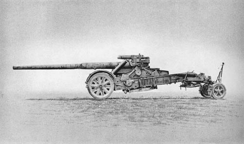
The 17 cm gun was developed to meet the need for a long-range mobile gun. Although the gun and carriage weigh 19.25 tons, the piece can be put in and taken out of action very quickly and with little effort.

The tube, usually transported separately from the rest of the weapon, is of the built-up type consisting of a main tube, locking ring, breech jacket, and breech ring. A manually operated breechblock is of the horizontal sliding wedge type with six rollers mounted almost flush with the bottom face to decrease the surface contact area. Extractors and firing mechanism are of conventional heavy German artillery design.

One unusual feature of the Mrs. Laf. 18 is that two recoil mechanisms absorb the shock of firing. A variable hydropneumatic recoil mechanism with the buffer cylinder within the cradle, and the recuperator cylinder mounted above the tube permits recoil of the gun; and another recoil mechanism mounted in the bottom carriage permits recoil of the upper carriage.

The gun is mounted on the 21 cm Mrs. Laf. carriage which has four hard rubber tired wheels. As there is no spade, the trails rest on an oblong float which houses an arc that permits 16° of traverse by means of a traversing handwheel. The firing platform when fully lowered fits into two sockets in the bottom carriage. Three rollers on vertical legs rest on the platform stabilizing the weight. The rear roller is mounted on a jack screw threaded leg. When more traverse is desired than that permitted by the arc, this roller is screwed down, lifting the float clear of the ground. One man, with the aid of a trail spike, can then swing the entire carriage about the firing platform 360°.

The prime mover for this weapon is reported to be the Sd Kfz. 8 semitracked vehicle.

SPECIFICATIONS

Caliber     172.5 mm (6.79 ins.)
Weight of weapon (firing)19.25 tons
Length of tube46 cal.
Breech mechanismHorizontal sliding block
Firing mechanismContinuous pull
Recoil mechanismTwo independent hydropneumatic systems—variable
Length of recoil of the piece at 50° (normal)33.86 ins.
Length of recoil of top carriage at 10° (normal)49.21 ins.
RiflingIncreasing R.H. twist—4° 16′ 40″ to 5° 58′ 42″—48 lands and grooves
Chamber capacity
   Shell KGr 392,538.6 cu. ins.
   Shell KGr 38 (Hb)2,513.2 cu. ins.
Muzzle velocity138 lb. shell—3035 f/s
Range (maximum)138 lb. shell—32,370 yds.
M.V.150 lb. shell—2821 f/s
Range (maximum)150 lb. shell—30,621 yds.
Elevation50°
Depression-1°
Traverse (carriage)16° (360° by using the pivot platform)
SightsIndependent type using combination of range drum and panoramic sight mount—left trunnion.
AmmunitionTwo semifixed high-explosive rounds
   K. Gr. 39150 lb.
   K. Gr. 38 (hb)138 lb.

German: p. 103

Categories
German

10.5 cm L.G. 40: Recoilless Gun

10.5 cm L.G. 40: Recoilless Gun

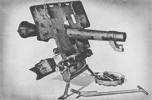
There are two known types of 10.5 cm recoilless guns in use by the German Army. The L.G. 40, formerly known as the L.G. 2 Kp., appears to be the type most frequently used. To prevent casualties, special precaution must be taken by the gun crew when firing the recoilless gun.

The barrel is screwed into the breech ring. This ring, with attachments, is composed of three parts : the breech ring proper, cylindrical in shape and approximately 43.5 cm in length; the rear portion which is hinged to the breech ring proper and swings to the right to permit loading; and the cone, approximately 41.2 cm in length, which is in one piece with the swiveling rear portion of the breech ring. At the right side of the breech ring is a boring which houses the striker mechanism. The upper surface of the breech ring is prepared for a clinometer.

The carriage consists of a crosshead and axle bar with torsion springs. Two spades under the crosshead, and a rectangular girder trail fitted with a spade, serve to give the carriage proper balance for firing. A tool box is located in the center portion of the trail. The shield, which is mounted on brackets just below the trunnion bearings, is in two parts and is fitted with sliding securing bars at top and bottom.

Both elevating and traversing mechanisms are situated on the lower left-hand side of the carriage. Two boxes, apparently for sighting gear, are also attached to the left of the carriage, but no sights were captured with the gun.

The 10.5 cm L.G. 42, previously known as the L.G. 2 Rh., is probably a later model of the L.G. 40, but none has been captured as yet.

SPECIFICATIONS

L.G. 40
Caliber       10.5 cm
Weight in action854 lb.
Length of piece (including cone)1,902 mm
Muzzle velocity1,105 f/s—H.E. rd.
1,224 f/s—hollow charge rd.
Range (max.)6,600 yds.
Range, effective (max.)1,660 yds.—hollow charge rd.
Elevation-15° to 40°
Traverse40° either way
L.G. 42
Muzzle velocity1,099 f/s—H.E. rd.
 1,236 f/s—hollow charge rd.
Range (max.)8,695 yds.
AmmunitionH.E. — F.H. Gr. 41 fuzed with either A.Z. 23 v (0.15) or Dopp. Z. s/60
  Hollow charge — 10 cm Gr. 39 fuzed with A.Z. 38 and using the same charge as for the F.H. Gr. 41

German: p. 110

Categories
German

10 cm K. 18: Field Gun

10 cm K. 18: Field Gun

The 10 cm Field Gun K. 18 was at one time standard equipment for German Field Artillery. The barrel consists of a jacket, an exchangeable tube, and a screwed-on breech. The breech mechanism is a single-motion, crank-operated, horizontal sliding block type, fitted with a repeating trip-lock. All the usual safety devices are provided, and, in addition, the breech is secured when the buffer piston rod is disconnected from the gun.

The top carriage is arranged to traverse about a vertical pivot up to 30° right and left. The cradle is mounted on the top carriage by trunnions set far to the rear. Balance is maintained by a pair of equilibrators, one on each side of the weapon. The hydraulic buffer is housed in the cradle, whereas the hydropneumatic recuperator is situated above the gun.

The carriage, of split-trail construction, is so designed that the wheels and the two trail spades are able to adjust themselves to irregularities of the surface of the ground. The spring suspension may readily be put in action for traveling, and out of action for firing, by means of two handwheels. The piece may be transported by either motor vehicle or horses. For mechanical traction, rubber tires are fitted to the carriage.

A pointer or indicator system is used for sighting purposes. Ammunition used is a high-explosive shell with a TNT bursting charge.

SPECIFICATIONS

Caliber         105 mm (4.137 ins.)
Weight of gun 4,011.28 lb.
Length 17.9 ft.
Muzzle velocity (maximum) 2,660 f/s
Range 20,776 yds.
Elevation 45°
Depression
Traverse 60°

German: p. 107

Categories
Japanese

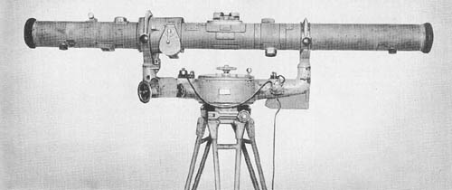
Stereoscopic 2 Meter Base Height Finder, Model 93

Stereoscopic 2 Meter Base Height Finder, Model 93

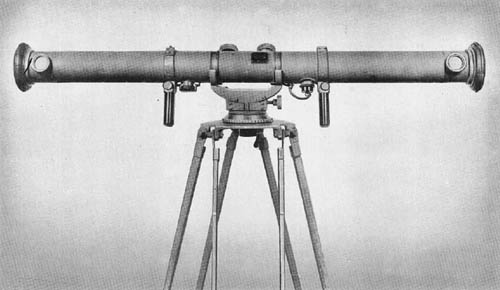
While primarily designed for use by antiaircraft batteries, a range finder of this type may be used by artillery units for determining horizontal as well as vertical range. The eyepieces are of the focusing type. Interpupillary distances may be set to suit the individual observer by means of a lever located on the right eyepiece. The eyepiece assembly also contains two ray filters.

The instrument consists of three major assemblies which are: the Range Finder Table, the Cradle, and the Tripod assembly. The outer tube is made of seamless steel tubing and has seven openings for adjustments. In addition, there are other openings for the eyepiece assembly, wedge windows, infinity correction lens assemblies, range knob, height of image knob, correction wedge assembly, range drum window, and reticle light windows. The optical bar is made of seamless machined steel and represents better machine work than most Japanese fire control instruments.

SPECIFICATIONS

Power         20 diameters
Field of view 2° 15′
Interpupillary setting 56 mm to 74 mm
Diopter adjustment +2 to -4
Limits of range measuring 400 to 20,000 yds.
Base length 2 meters
Overall length 7 ft., 5 5/8 ins.
Weight 201 lbs.
Cradle
   Overall length 36 ins.
   Distance between trunnions 34 11/16 ins.
   Height 23 ins. (approx.)
   Weight 162 lbs.
Tripod
   Overall height 32 ins.
   Weight 100 lbs.

Japanese: p. 183 (March 1, 1945)

Categories
Japanese

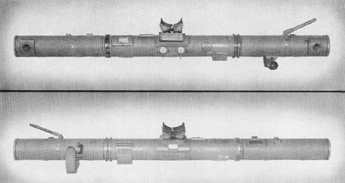
Stereoscopic 2 Meter Base Range Finder Model 97 Type 2

Stereoscopic 2 Meter Base Range Finder Model 97 Type 2

This range finder is believed to be designed for use with seacoast defenses. It is provided with an elbow telescope for tracking purposes and a graphical computer for converting slant range to altitude.

A number of its design features are quite similar to those in the Japanese 2 meter base Height Finder. Similarities are noted in the penta prism mounting, central prism assembly, reticle and eyepiece assemblies, night lighting of scales, and the filter assembly. The instrument is constructed with an outer tube, optical tube, and two tubular diaphragms, all of steel. The outer tube is covered with asbestos treated canvas. The tracking telescope provided with this instrument has a power of 10 diameters and a 5 degree field of view. The body is made of cast aluminum. The tracking telescope is attached to the main instrument by means of a dovetail bracket and is locked in place by a spring latch.

Another accessory, the graphical altitude computor, consists of a pendulum arm inclosed in a circular holder. The pendulum is graduated with a vertical scale in increments of 50 meters from 100 to 1,000 meters, which represents slant range. Angle of site is indicated by a graduated scale on the face of the holder. The cradle has the trunnion bearing arms cast as an integral part of the body. The eyeguard assembly is a copy of the Carl Zeiss design.

SPECIFICATIONS

Power        24
Field of view Undetermined
Diameter of entrance pupil 1.9 ins.
Diameter of exit pupil .08 ins.
Base length 2 meters
Diopter movement +2 to -4 diopters
Measuring limits 500 to 20,000 meters
Inter-trunnion distance 35 1/2 ins.
Overall length 86 ins.
Weight 148 lbs.

Japanese: p. 182 (March 1, 1945)

Categories
Japanese

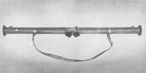
1 Meter Base Range Finder, Model 94

1 Meter Base Range Finder, Model 94

This instrument is a one-meter base, stereoscopic, horizontal base range finder. Ranges are read directly from the reticles.

The outer tube is made of cast aluminum. The inner tube, made of seamless steel tubing, is supported in the outer tube by means of a gimbal joint. The height of image knob is located on the right end of the instrument; the range correction knob is on the left side. The lighting window of the reticle is above the eyepiece plate. An auxiliary open sight is located above the right eyepiece.

Uniform adjustment of interpupillary distance is obtained by connecting the two eyepieces with steel tape forming a figure 8. Rhomboid prisms keep the optical axes of the eyepieces in alignment with the reticles. The penta prism assemblies are held to circular plates which may be rotated to eliminate tilt of image and place both images at the same height in the field of view.

SPECIFICATIONS

Power         8 diameters
Field of view
Base length 1 meter
Diopter movement + and – 4 diopters
Interpupillary setting 55 to 75 mm
Overall length 43 3/4 ins.
Weight 6 lbs., 13 ozs.
Serial number 1218
Measuring limits 250 to 8,000 yds.

Japanese: p. 181 (March 1, 1945)

Categories
Japanese

75 cm Base Range Finder

75 cm Base Range Finder (Japanese)

This instrument is very similar to the 80 cm base range finder, Keuffel and Esser Model 1918. It also resembles the design of the Barr and Stroud instrument. It is, therefore, assumed that it is used much the same as the American 80 cm base, M1914M1 Range Finder. It is a coincidence type range finder with a split field of view, and is used by light field artillery units.

The ocular prism consists of three optical components cemented together resembling the arrangement in the American 1 meter base range finder, M1916. The eyepiece assembly is of the symmetrical type. The halving plate is a thick piece of optical glass with plano parallel surfaces. The measuring wedge and range scale are a single assembly. The latter is illuminated by the light rays entering through the range scale illuminating window, and reflected by a mirror. The objectives, installed as matched pairs are burnished in their cells. The penta prisms and wedge windows resemble those used in American range finders.

An effort has been made, through a bushing in the center of the buffer assemblies, to desiccate the instrument. It is not believed that the eyepiece assemblies can be sufficiently sealed to make this effective.

The tripod is lightly constructed and has no locking device for the legs. The tripod mount permits the range finder to be locked or rotated in azimuth. There is also a leveling device, but no level vial.

SPECIFICATIONS

Base length       75 cm
Magnification12 power
Range100 to 10,000 yds.
Field of viewVertical 2°—horizontal 3°
Weight of range finder9 lbs.
Weight of carrying case6 lbs.

Japanese: p. 180 (March 1, 1945)