-

-
Popular Posts
-
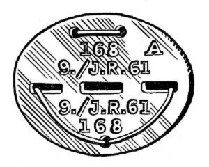 Erkennungsmarke (German Dog Tag)
From Handbook on German Army Identification, U.S. Milit...
Erkennungsmarke (German Dog Tag)
From Handbook on German Army Identification, U.S. Milit...
-
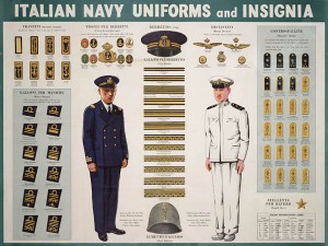 Italian Navy Uniforms and Insignia
:
CON...
Italian Navy Uniforms and Insignia
Italian Navy Uniforms and Insignia:
CON...
-
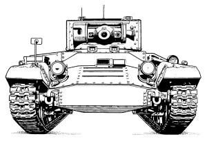 Valentine Tank Illustrations
Front and side views of the Valentine Tank (officially...
Valentine Tank Illustrations
Front and side views of the Valentine Tank (officially...
-
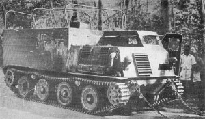 Japanese Type 1 Ho-Ki Armored Personnel Carrier
The Japanese produced a limited number of the innovativ...
Japanese Type 1 Ho-Ki Armored Personnel Carrier
The Japanese produced a limited number of the innovativ...
-
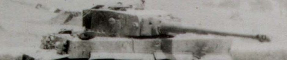
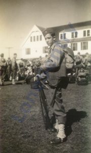 Early-War Uniform
A private photograph from 1942 showing details of the e...
Early-War Uniform
A private photograph from 1942 showing details of the e...
-
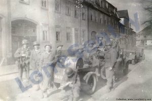 89th Infantry Division in Germany
Photographs of the U.S. Army's 89th Infantry ...
89th Infantry Division in Germany
Photographs of the U.S. Army's 89th Infantry ...
-
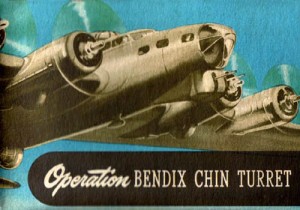 Bendix Chin Turret
Bendix manual on the Operation and Maintenance of the B...
Bendix Chin Turret
Bendix manual on the Operation and Maintenance of the B...
-
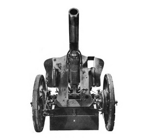 German 105-mm Howitzer
Three views of the German 105-mm howitzer (10.5 cm leFH...
German 105-mm Howitzer
Three views of the German 105-mm howitzer (10.5 cm leFH...
-
 How’s Your Sherman, Herman?
M4 Sherman Tank modification and upgrades from Army Mot...
How’s Your Sherman, Herman?
M4 Sherman Tank modification and upgrades from Army Mot...
-
Tag Archives: research
Air Attack at Hunt’s Gap
The following correspondent’s report from the UP (United Press) describes the fighting at Hunt’s Gap in Tunisia in February-March 1943. Compare this account of the battle to the German commander Oberst. Rudolf Lang’s account and British observer Howard Marshall’s account. … Continue reading
Posted in aircraft, armor, research
Tagged aircraft, armor, beja, hunt's gap, ksar mezouar, research, sidi nsir, spzabt 501, tiger, tunisia
1 Comment
SO-7M Radar
The following report on the WW2 SO-7M truck-mounted surface search radar was published in the September 1944 issue of C.I.C. (Combat Information Center) published by the U.S. Office of the Chief of Naval Operations. What the SO-7M can do… The … Continue reading
Posted in miscellaneous, research, training
Tagged equipment, radar, research, search radar, SO-7M, training
1 Comment
The Bombing of Germany
PBS’ American Experience presents The Bombing of Germany, an excellent documentary on the American and British bombing of Germany in WWII with extensive color footage and veteran interviews. Documentary Home Page Full Video Online at PBS Government Film: Memphis Belle … Continue reading
Removing Inner Bogie Wheels on Horizontal-Volute Suspension
Instructions for removing the inner bogie wheels on the M4 tank with horizontal-volute spring suspension (HVSS) from Army Motors, Vol. 5, No. 11, February 1945. SPECIAL TOOLS FOR YOUR NEW H.S./M.F.T. Meaning: Horizontal-Suspension M-Four Tank. If that is your brand, this SOP is … Continue reading
Posted in armor, miscellaneous, research
Tagged armor, HVSS, maintenance, ordnance, repair, research, suspension
1 Comment
Jacques Littlefield Collection (MVTF)
The Military Vehicle Technology Foundation (MVTF), founded by Jacques Littlefield, is a large collection of tanks and military vehicles housed in Portola Valley, California. MVTF was established in 1998 to establish and preserve a collection of vehicles to serve the … Continue reading
Posted in miscellaneous, research
Tagged armor, collection, jacques littlefield, museum, MVTF, research
1 Comment
F4U Corsair in Action
Squadron Signal Publications have just announced their newest “In Action” book on the F4U Corsair. This new volume on the F4U Corsair updates Squadron Signal’s previous books on the well-known aircraft. SS1220: F4U Corsair In Action by Jim Sullivan. From … Continue reading
Posted in publications, research
Tagged book, corsair, F4U, publications, research, squadron signal
2 Comments
143rd AAA Gun Battalion
The website Army Book of Memories tells the story of the 143rd AAA Gun Battalion during WWII from training through the fighting in the Ardennes Offensive and on to V-E Day. The website also includes photographs and a copy of … Continue reading
Posted in artillery, publications
Tagged 143rd, AAA, antiaircraft, links, publications, research, unit history
1 Comment
Canfora Panther
Canfora will soon be taking preorders on their new book Panther which will combine models and dioramas with historical research and photographs. Panther has an impressive list of contributors including Hilary Doyle, Mirko Bayerl, Phil Stutcinskas, Lester Plaskitt, Gunnar Jansson, … Continue reading
Posted in publications, research, scale models
Tagged book, canfora, hobby, panther, reference, research, scale models
1 Comment
Vehicle Signs and Shoulder Titles
The following short remarks on vehicle unit markings and unit uniform markings was printed in “Intelligence Lessons from North Africa, Operation Torch” by the Office of Assistant Chief of Staff, G-2, Allied Force Headquarters, March 1943. Vehicle Signs and Shoulder … Continue reading
Posted in miscellaneous, publications, research
Tagged intelligence, markings, north africa, research, security, torch
Comments Off on Vehicle Signs and Shoulder Titles
How’s Your Sherman, Herman?
M4 Sherman Tank modification and upgrades from Army Motors, Maintenance Branch, Office of Chief of Ordnance, Vol. 5, No. 1, April 1944: If it’s a Tank, Medium, M4—here are the visible changes that should have been made by now. Check … Continue reading
Posted in armor, research
Tagged armor, army motors, m4, maintenance, ordnance, research, sherman, tank, technical
3 Comments